Proton Calorimetry/Experimental Runs/2018/Nov16-18: Difference between revisions
| Line 3: | Line 3: | ||
== Equipment List == | == Equipment List == | ||
{| class="wikitable" | |||
! style="text-align: center;" | Item | |||
! style="text-align: center;" | Notes | |||
|- | |||
| style="text-align: center;" | Network Hub | |||
| style="text-align: center;" | Set in control room to take output from experimental room ethernet switcher. Control laptops connected via ethernet or 5GHz WiFi. | |||
|- | |||
| style="text-align: center;" | Control Laptop x2 | |||
| style="text-align: center;" | | |||
|- | |||
| style="text-align: center;" | DAQ desktop PC | |||
| style="text-align: center;" | | |||
|- | |||
| style="text-align: center;" | Ethernet Switcher | |||
| style="text-align: center;" | Set in experiment room and connected DAQ desktop PC. Output sent to control room Network Hub. | |||
|- | |||
| style="text-align: center;" | Ethernet Cable x 5 | |||
| style="text-align: center;" | To connect DAQ PC to switcher, switcher to Network Hub (long cable), 2 laptops to Network Hub, if scope: scope to switcher. | |||
|} | |||
==== Range Detector Experiment ==== | ==== Range Detector Experiment ==== | ||
| Line 88: | Line 107: | ||
| style="text-align: center;" | Wipes | | style="text-align: center;" | Wipes | ||
| style="text-align: center;" | For removing optical gel | | style="text-align: center;" | For removing optical gel | ||
|} | |} | ||
Revision as of 12:17, 14 November 2018
2 night shifts with range calorimeter and single PMT module.
Equipment List
| Item | Notes |
|---|---|
| Network Hub | Set in control room to take output from experimental room ethernet switcher. Control laptops connected via ethernet or 5GHz WiFi. |
| Control Laptop x2 | |
| DAQ desktop PC | |
| Ethernet Switcher | Set in experiment room and connected DAQ desktop PC. Output sent to control room Network Hub. |
| Ethernet Cable x 5 | To connect DAQ PC to switcher, switcher to Network Hub (long cable), 2 laptops to Network Hub, if scope: scope to switcher. |
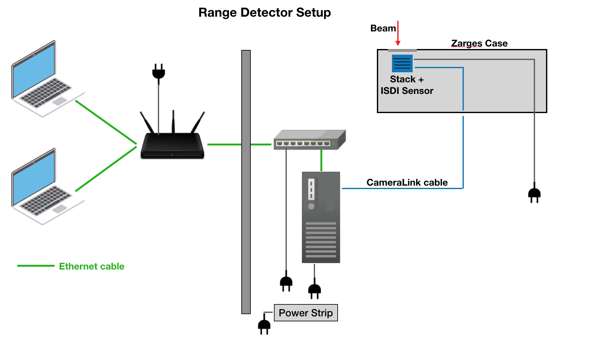
Range Detector Experiment
| Item | Notes |
|---|---|
| Portable Enclosure | Modified Big Zarges Waterproof Wheeled Equipment Case.
Features mount for scintillator and PMT, opening for beam, and ports for SHV, BNC, SMA, Camera Link cables. |
| Scintillator stack | 15 x 2 mm, 15 x 2.6 mm and 1 x 3 mm sheets in ascending order from the back of the scintillator to the front/beam. Except for sheet number 21 (2mm) which is placed at the end (away end from the beam) of the stack because of a crack in the sheet. Sheet numbers from front to end (in beam direction): 31,25,24,23,20,16,12,11,9,8,6,5,4,3,2,1,30,29,28,27,26,22,19,18,17,15,14,13,10,7,21. |
| ISDI CMOS sensor | sensor pixel dimension: 1030 x 1536. NO optical grease between scintillator and sensor. Connected to DAQ PC via Camera Link cable. |
| DAQ desktop PC | Controls sensor aquisition. |
| Gloves | For handling scintillator |
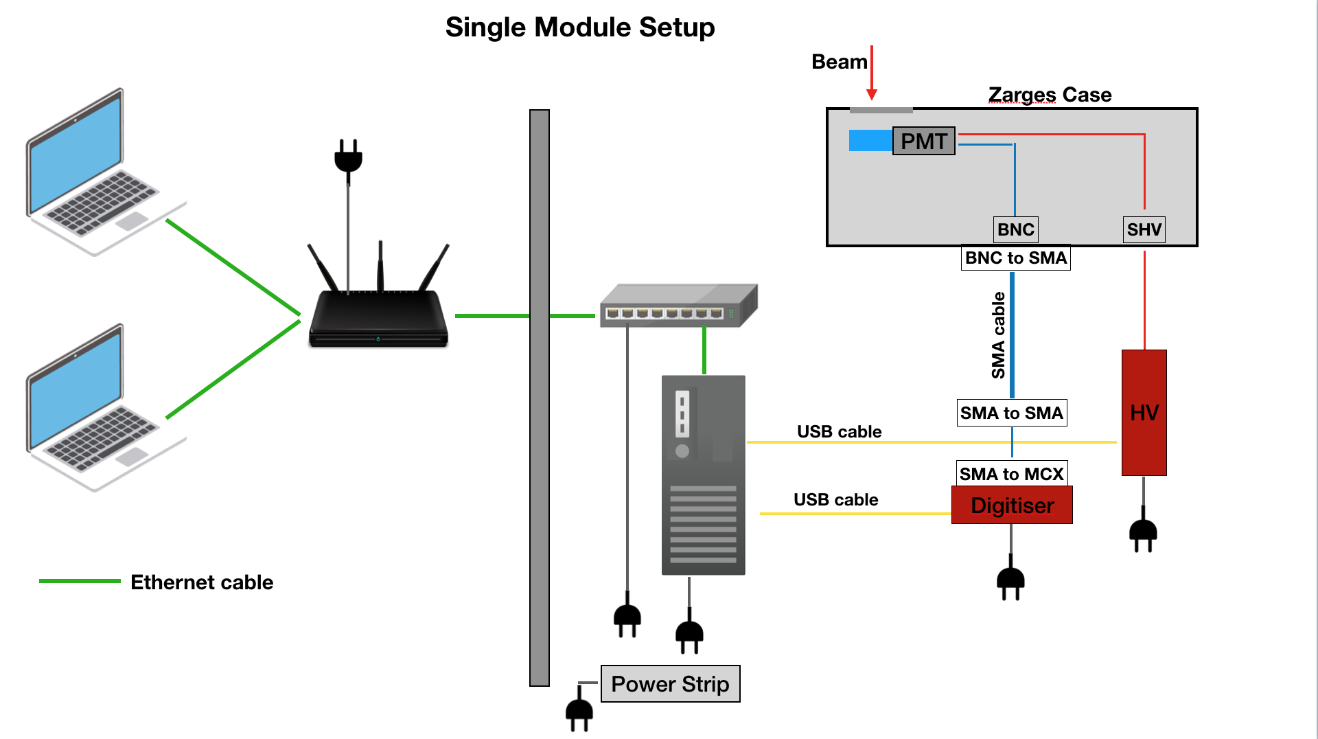
Single Module Experiment
| Item | Notes | ||
|---|---|---|---|
| Single Module Scintillator Blocks x5 | 1cm/3cm/5cm x 10cm x 10cm standard scintillator block. Optical gel required to couple Scintillator to PMT. 5cm and 3cm with black wrapping. 5cm, 3cm, 1cm mylar wrapping. | ||
| Photomultiplier Tube | Hamamatsu R13089 2" | ||
| Portable Enclosure | Modified Big Zarges Waterproof Wheeled Equipment Case.
Features mount for scintillator and PMT, opening for beam, and ports for SHV, BNC, SMA, Camera Link cables. | ||
| Caen DT5751 Digitiser | Records PMT output, connected via SMA-MCX conversion. Used channel 3. | ||
| Caen NDT1470 HV Supply | Supplies HV to PMT | ||
| USB Cable | Caen units to DAQ PC | ||
| DAQ desktop PC | Controls Caen HV supply; records data from Caen digitiser. | ||
| Male-to-Male SMA Cable x3 | Signal from enclosure port to digitiser. Short/Light and Long cables connected via SMA to SMA connector. If scope used: SMA splitter + SMA cable + SMA to BNC adaptor used to split the input signal and send it both to scope and digitiser. |
DC-4200 MHz Signal Splitter | Splits SMA signal to two SMA signals – sent to Oscilloscope and Digitiser. |
| Female-to-Female SMA Connector | Connects Long SMA cable to Short/Light SMA cable. | ||
| Female-to-Female BNC to SMA Connector x2 | From case to SMA cable (or splitter); From SMA cable to scope. | ||
| Male SMA to Male MCX Adaptor | Sends output from SMA cable to Digitiser | ||
| Gloves | For handling scintillator | ||
| Optical gel | For coupling scintillator to PMT | ||
| Wipes | For removing optical gel |
Experiment List
16–17th November
ISDI sensor + scintillator stack
17–18th November
Single module
Experiment Log
Beam Tests
16–17th November
| Run Number | High Voltage (V) | Trigger Level (mV) | Trigger Source | Beam Current / Rate | Collimator | Filename | Notes |
|---|---|---|---|---|---|---|---|
| 00 | -900 | 70, +ve | Tracker (C2) | 170pA/~10 kHz | 2 mm centred | run00_2mmCCol_160pA_TrackTrig | First test of tracker/PMT synchronisation |