Proton Calorimetry/Experimental Runs/2019/Apr12-15: Difference between revisions
(Created page with "page created?") |
No edit summary |
||
| Line 1: | Line 1: | ||
UPDATE THIS PAGE | |||
2 night shifts with range calorimeter and single PMT module. | |||
== Equipment List == | |||
{| class="wikitable" | |||
! style="text-align: center;" | Item | |||
! style="text-align: center;" | Notes | |||
|- | |||
| style="text-align: center;" | Network Hub | |||
| style="text-align: center;" | Set in control room to take output from experimental room ethernet switcher. Control laptops connected via ethernet or 5GHz WiFi. | |||
|- | |||
| style="text-align: center;" | Control Laptop x2 | |||
| style="text-align: center;" | | |||
|- | |||
| style="text-align: center;" | DAQ desktop PC | |||
| style="text-align: center;" | | |||
|- | |||
| style="text-align: center;" | Ethernet Switcher | |||
| style="text-align: center;" | Set in experiment room and connected DAQ desktop PC. Output sent to control room Network Hub. | |||
|- | |||
| style="text-align: center;" | Ethernet Cable x 5 | |||
| style="text-align: center;" | To connect DAQ PC to switcher, switcher to Network Hub (long cable), 2 laptops to Network Hub, if scope: scope to switcher. | |||
|} | |||
==== Range Detector Experiment ==== | |||
<div class="image600px" style="text-align: center;"> | |||
[http://www.hep.ucl.ac.uk/pbt/wikiData/images/Heidelberg_Nov2018/RangeExperiment.png http://www.hep.ucl.ac.uk/pbt/wikiData/images/Heidelberg_Nov2018/RangeExperiment.png] | |||
</div> | |||
{| class="wikitable" | |||
! style="text-align: center;" | Item | |||
! style="text-align: center;" | Notes | |||
|- | |||
| style="text-align: center;" | Portable Enclosure | |||
| style="text-align: center;" | Modified Big Zarges Waterproof Wheeled Equipment Case. | |||
Features mount for scintillator and PMT, opening for beam, and ports for SHV, BNC, SMA, Camera Link cables. <br/> | |||
Hole for sensor powering. <br/> | |||
Mylar window with Al support mounted to internal face: approximately light-tight. | |||
|- | |||
| style="text-align: center;" | Scintillator stack | |||
| style="text-align: center;" | 14 x 2 mm, 15 x 2.6 mm and 20 x 3 mm sheets in ascending order from the front/beam of the end of the scintillator. Sheet 21 not used. Sheet numbers from front to end (in beam direction): 30,29,28,27,26,22,19,18,17,15,14,13,10,7,25,24,23,20,16,12,11,9,8,6,5,4,3,2,1,31,32,33,34,35,36,37,38,39,40,41,42,43,44,45,46,47,48,49,50. | |||
|- | |||
| style="text-align: center;" | ISDI CMOS sensor | |||
| style="text-align: center;" | sensor pixel dimension: 1030 x 1536. NO optical grease between scintillator and sensor. Connected to DAQ PC via Camera Link cable. | |||
|- | |||
| style="text-align: center;" | DAQ desktop PC | |||
| style="text-align: center;" | Controls sensor aquisition. | |||
|- | |||
| style="text-align: center;" | Gloves | |||
| style="text-align: center;" | For handling scintillator | |||
|} | |||
==== Single Module Experiment ==== | |||
<div class="image600px" style="text-align: center;"> | |||
[http://www.hep.ucl.ac.uk/pbt/wikiData/images/Heidelberg_Nov2018/SingleModuleExperiment.png http://www.hep.ucl.ac.uk/pbt/wikiData/images/Heidelberg_Nov2018/SingleModuleExperiment.png] | |||
</div> | |||
{| class="wikitable" | |||
! style="text-align: center;" | Item | |||
! style="text-align: center;" | Notes | |||
|- | |||
| style="text-align: center;" | Portable Enclosure | |||
| style="text-align: center;" | Modified Big Zarges Waterproof Wheeled Equipment Case. | |||
Features mount for scintillator and PMT, opening for beam, and ports for SHV, BNC, SMA, Camera Link cables. <br/> | |||
Hole for sensor powering. <br/> | |||
Mylar window with Al support mounted to internal face: approximately light-tight. <br/> | |||
BNC output from case connected to BNC to SMA adaptor. | |||
|- | |||
| style="text-align: center;" | Single Module Scintillator Blocks x5 | |||
| style="text-align: center;" | 1cm/3cm/5cm x 10cm x 10cm standard scintillator block. Optical gel required to couple Scintillator to PMT. 5cm and 3cm with black wrapping. 5cm, 3cm, 1cm mylar wrapping. | |||
|- | |||
| style="text-align: center;" | Photomultiplier Tube | |||
| style="text-align: center;" | Hamamatsu R13089 2" | |||
|- | |||
| style="text-align: center;" | Caen DT5751 Digitiser | |||
| style="text-align: center;" | Records PMT output, connected via SMA-MCX conversion. Used channel 3. | |||
|- | |||
| style="text-align: center;" | Caen NDT1470 HV Supply | |||
| style="text-align: center;" | Supplies HV to PMT | |||
|- | |||
| style="text-align: center;" | USB Cable | |||
| style="text-align: center;" | Caen units to DAQ PC | |||
|- | |||
| style="text-align: center;" | DAQ desktop PC | |||
| style="text-align: center;" | Controls Caen HV supply; records data from Caen digitiser. | |||
|- | |||
| style="text-align: center;" | Male-to-Male SMA Cable x3 | |||
| style="text-align: center;" | Signal from enclosure port to digitiser. Short/Light and Long cables connected via SMA to SMA connector.<br/> | |||
If scope used: SMA splitter + SMA cable + SMA to BNC adaptor used to split the input signal and send it both to scope and digitiser. | |||
|- | |||
| style="text-align: center;" | DC-4200 MHz Signal Splitter | |||
| style="text-align: center;" |Splits SMA signal to two SMA signals – sent to Oscilloscope and Digitiser. | |||
|- | |||
| style="text-align: center;" | Female-to-Female SMA Connector | |||
| style="text-align: center;" | Connects Long SMA cable to Short/Light SMA cable. | |||
|- | |||
| style="text-align: center;" | Female-to-Female BNC to SMA Connector x2 | |||
| style="text-align: center;" | From case to SMA cable (or splitter); From SMA cable to scope. | |||
|- | |||
| style="text-align: center;" | Male SMA to Male MCX Adaptor | |||
| style="text-align: center;" | Sends output from SMA cable to Digitiser | |||
|- | |||
| style="text-align: center;" | Gloves | |||
| style="text-align: center;" | For handling scintillator | |||
|- | |||
| style="text-align: center;" | Optical gel | |||
| style="text-align: center;" | For coupling scintillator to PMT | |||
|- | |||
| style="text-align: center;" | Wipes | |||
| style="text-align: center;" | For removing optical gel | |||
|} | |||
== Experiment List == | |||
=== 12–17th November === | |||
Range calorimeter measurements with ISDI sensor + scintillator stack. | |||
# Helium: | |||
## Background measurement. | |||
## Intensity check with 50.57 MeV/u pristine Bragg peak. | |||
## Shoot-through at 220.51 MeV/u for sensor intensity calibration. | |||
## Individual range measurements from 50.57 MeV/u (2.287cm) to 110 mm (=122.3 MeV/u) range: | |||
### 5mm steps from min to max. | |||
### 10 x 1mm steps from 50.57MeV/u upwards. (10 lowest energy steps; 50.57MeV/u, 51.79MeV/u, 52.97,54.14,55.30, 56.44, 57.54,58.64,59.74,60.80 MeV/u = 2.287, 2.388,2.488,2.587,2.587,2.788,2.887,2.987,3.088,3.187 cm) | |||
### 10 x 1mm steps from ~100mm downwards. (the 10 step down from 115.9 MeV: Ranges : 10.09,99.89,9.889,9.789,9.689,9.589,9.489,9.388,9.289,9.189) | |||
## SOBP with single pixel stripe in single acquisition. | |||
# Carbon: | |||
## Background measurement. | |||
## Intensity check with 88.83 MeV/u pristine Bragg peak. | |||
## Shoot-through at 430.10 MeV/u for sensor intensity calibration. | |||
## Individual range measurements from 88.83 MeV/u to 110 mm range: | |||
### 5mm steps from min to max. | |||
### 10 x 1mm steps from 88.83 MeV/u upwards. | |||
### 10 x 1mm steps from ~100mm downwards. | |||
## SOBP with single pixel stripe in single acquisition. | |||
# Proton: | |||
## Background measurement. | |||
## Intensity check with 48.12 MeV pristine Bragg peak. | |||
## Shoot-through at 221.06 MeV/u for sensor intensity calibration. | |||
## Individual range measurements from 48.12 MeV/u to 110 mm range: | |||
### 5mm steps from min to max. | |||
### 10 x 1mm steps from 48.12 MeV/u upwards. | |||
### 10 x 1mm steps from ~100mm downwards. | |||
## SOBP with single pixel stripe in single acquisition. | |||
## Position scan at 100mm with 30mm transverse offset in both positive and negative ''x''. | |||
'''Oxygen measurements planned but not requested''': | |||
# Background measurement. | |||
# Intensity check with 103.77 MeV pristine Bragg peak. | |||
# Shoot-through at 514.82 MeV/u for sensor intensity calibration. | |||
# Individual range measurements from 103.77 MeV/u to 110 mm range: | |||
## 5mm steps from min to max. | |||
## 10 x 1mm steps from 103.77 MeV/u upwards. | |||
## 10 x 1mm steps from ~100mm downwards. | |||
# SOBP with single pixel stripe in single acquisition. | |||
=== 17–18th November === | |||
==== Range calorimeter measurements with ISDI sensor + scintillator stack ==== | |||
# Helium: | |||
## Background measurement. | |||
## Intensity check with 50.57 MeV/u pristine Bragg peak. | |||
## Shoot-through at 220.51 MeV/u for sensor intensity calibration. | |||
## SOBP measurements: | |||
### Correct SOBP measurement with 100mm distal edge using equal particle rate but clinical weighting for each layer with 3x3 spot grid. | |||
### Correct SOBP measurement with 100mm distal edge using clinical weighting with approx. equal time to deliver each each layer with single on-axis spot. | |||
### Faked SOBP measurement with 100mm distal edge using equal particle rate and equal weighting for each spot with single on-axis spot. | |||
### Both measurements SOBP with single pixel stripe in single acquisition: 6x1,536 pixel area; approx 1m50s acquisition time. | |||
# Mixed particle tests: | |||
## Carbon clinical SOBP with 100mm distal edge using equal particle rate but clinical weighting for 15 layers with 2mm range spacing and 3x3 spot grid. | |||
## Carbon faked SOBP with 100mm distal edge using equal particle rate and equal weighting for each layer with single on-axis spot for 10 layers with 3mm layer spacing. | |||
## Helium replica of 100mm Carbon clinical SOBP (260mm distal edge) with 10 layers with 8/9mm layer spacing (closest approximation of 3mm Carbon layer spacing); equal particle rate with clinical weighting and 3x3 spot grid. | |||
## Helium replica of 100mm Carbon faked SOBP (260mm distal edge) using equal particle rate and equal weighting for each layer with single on-axis spot for 10 layers with 8/9mm layer spacing. | |||
## Repeat measurements with 50mm PMMA sheets until Helium SOBP fully contained in detector. | |||
## Add 30mm PMMA sheet and repeat Helium measurements in small transverse steps (tumour motion simulation). | |||
==Experiment Log== | |||
PMMA blocks are 50mm thick. Water Equivalent Thickness is 57.81mm. | |||
== Beam Tests == | |||
=== 12–13th April === | |||
Beam focus ranges from step 1 (smallest) to step 4 (of 6). | |||
==== Helium ion beam ==== | |||
full sensor area | |||
{| class="wikitable" | |||
!Run number | |||
!Full Well Mode | |||
!Beam Energy (MeV/u) | |||
!Range (estimated) | |||
!N particles | |||
!Spot size (mm) | |||
!Test type | |||
!Comments | |||
!Thumbnail | |||
|- | |||
|N || well mode || Energy MeV/u || Range || particles || Spot FWHM || test || comments || - | | |||
|- | |||
|00 || None || None || - || None || None || - || background || - | | |||
|- | |||
|01 || low || 50.57 || 22.9 || 10^8 || 18.6|| He || low energy, low intensity || - | | |||
|- | |||
|} | |||
==== Carbon ion beam ==== | |||
full sensor | |||
{| class="wikitable" | |||
!Run number | |||
!Full Well Mode | |||
!Beam Energy (MeV/u) | |||
!Range (estimated) | |||
!N particles | |||
!Spot size (mm) | |||
!Test type | |||
!Comments | |||
!Thumbnail | |||
|- | |||
|N || well mode || Energy MeV/u || Range || particles || Spot FWHM || test || comments || - | | |||
|- | |||
|44 || high || None || - || None || None || - || background || - | | |||
|- | |||
|} | |||
==== Proton beam ==== | |||
full sensor | |||
{| class="wikitable" | |||
!Run number | |||
!Full Well Mode | |||
!Beam Energy (MeV/u) | |||
!Range (estimated) | |||
!N particles | |||
!Spot size (mm) | |||
!Test type | |||
!Comments | |||
!Thumbnail | |||
|- | |||
|N || well mode || Energy MeV/u || Range || particles || Spot FWHM || test || comments || - | | |||
|- | |||
|79 || high || None || - || None || None || - || background || - | | |||
|- | |||
|} | |||
=== 14–15th April === | |||
Beam focus ranges from step 1 (smallest) to step 4 (of 6). | |||
==== Helium ion beam ==== | |||
full sensor area | |||
{| class="wikitable" | |||
!Run number | |||
!Full Well Mode | |||
!Beam Energy (MeV/u) | |||
!Range (estimated) | |||
!N ions /s | |||
!Spot size (mm) | |||
!Test type | |||
!Comments | |||
!Thumbnail | |||
|- | |||
|N || well mode || Energy MeV/u || Range || ions/s || Spot FWHM || test || comments || - | | |||
|- | |||
|00 || high || None || - || None || None || - || background || - | | |||
|- | |||
|01 || high || 50.57 || 22.9 || 8x10^8 || 18.6 || He || low energy, max clinical intensity || - | | |||
|} | |||
==== Mixed Helium and Carbon ions beam ==== | |||
full sensor | |||
{| class="wikitable" | |||
!Run number | |||
!Full Well Mode | |||
!Beam Energy (MeV/u) | |||
!Range (estimated) | |||
!N particles | |||
!Spot size (mm) | |||
!Test type | |||
!Comments | |||
!Thumbnail | |||
|- | |||
|N || well mode || Energy MeV/u || Range || particles || Spot FWHM || test || comments || - | | |||
|- | |||
|09 || high || 182.32 - 222.31 || 74.4 - 104.5 || - || 5.5 - 4.7 || C || Real Clinical SOBP, 6 pixel rows (512 offset), 100mm distal edge using clinical weighting with approx. equal time to deliver each layer with single on-axis spot. || - | | |||
|} | |||
Revision as of 16:28, 9 April 2019
UPDATE THIS PAGE 2 night shifts with range calorimeter and single PMT module.
Equipment List
| Item | Notes |
|---|---|
| Network Hub | Set in control room to take output from experimental room ethernet switcher. Control laptops connected via ethernet or 5GHz WiFi. |
| Control Laptop x2 | |
| DAQ desktop PC | |
| Ethernet Switcher | Set in experiment room and connected DAQ desktop PC. Output sent to control room Network Hub. |
| Ethernet Cable x 5 | To connect DAQ PC to switcher, switcher to Network Hub (long cable), 2 laptops to Network Hub, if scope: scope to switcher. |
Range Detector Experiment
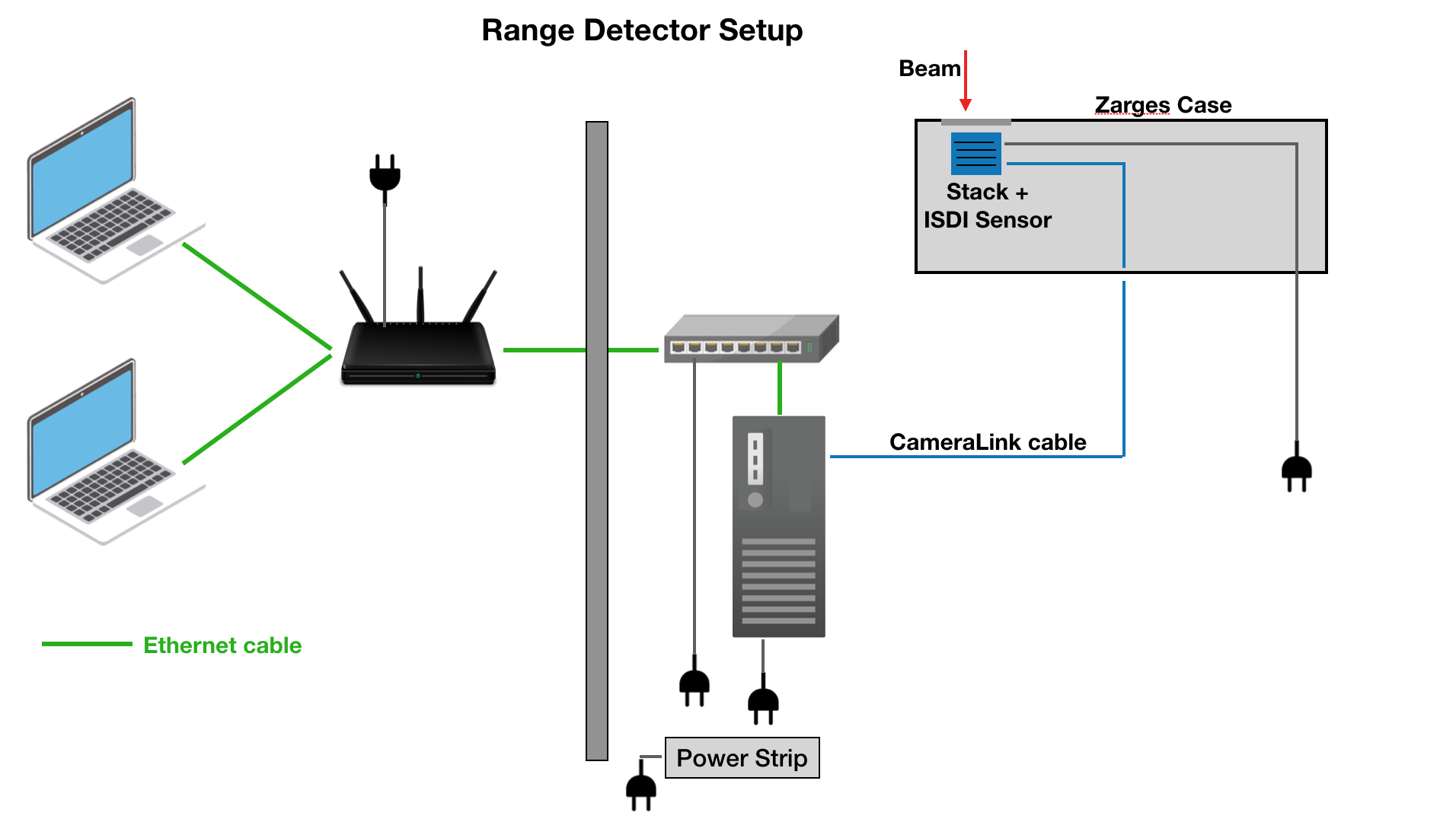
| Item | Notes |
|---|---|
| Portable Enclosure | Modified Big Zarges Waterproof Wheeled Equipment Case.
Features mount for scintillator and PMT, opening for beam, and ports for SHV, BNC, SMA, Camera Link cables. |
| Scintillator stack | 14 x 2 mm, 15 x 2.6 mm and 20 x 3 mm sheets in ascending order from the front/beam of the end of the scintillator. Sheet 21 not used. Sheet numbers from front to end (in beam direction): 30,29,28,27,26,22,19,18,17,15,14,13,10,7,25,24,23,20,16,12,11,9,8,6,5,4,3,2,1,31,32,33,34,35,36,37,38,39,40,41,42,43,44,45,46,47,48,49,50. |
| ISDI CMOS sensor | sensor pixel dimension: 1030 x 1536. NO optical grease between scintillator and sensor. Connected to DAQ PC via Camera Link cable. |
| DAQ desktop PC | Controls sensor aquisition. |
| Gloves | For handling scintillator |
Single Module Experiment
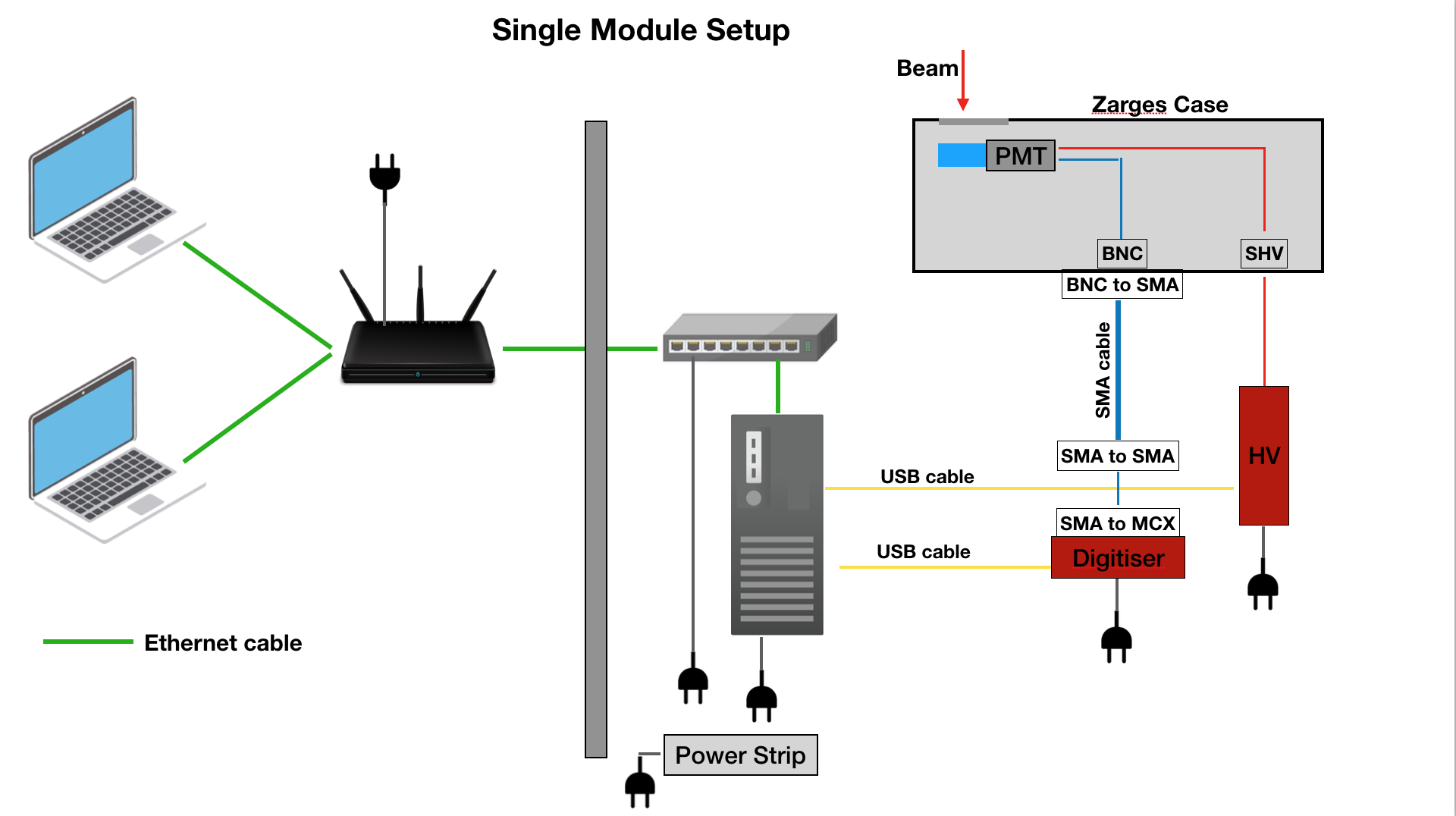
| Item | Notes |
|---|---|
| Portable Enclosure | Modified Big Zarges Waterproof Wheeled Equipment Case.
Features mount for scintillator and PMT, opening for beam, and ports for SHV, BNC, SMA, Camera Link cables. |
| Single Module Scintillator Blocks x5 | 1cm/3cm/5cm x 10cm x 10cm standard scintillator block. Optical gel required to couple Scintillator to PMT. 5cm and 3cm with black wrapping. 5cm, 3cm, 1cm mylar wrapping. |
| Photomultiplier Tube | Hamamatsu R13089 2" |
| Caen DT5751 Digitiser | Records PMT output, connected via SMA-MCX conversion. Used channel 3. |
| Caen NDT1470 HV Supply | Supplies HV to PMT |
| USB Cable | Caen units to DAQ PC |
| DAQ desktop PC | Controls Caen HV supply; records data from Caen digitiser. |
| Male-to-Male SMA Cable x3 | Signal from enclosure port to digitiser. Short/Light and Long cables connected via SMA to SMA connector. If scope used: SMA splitter + SMA cable + SMA to BNC adaptor used to split the input signal and send it both to scope and digitiser. |
| DC-4200 MHz Signal Splitter | Splits SMA signal to two SMA signals – sent to Oscilloscope and Digitiser. |
| Female-to-Female SMA Connector | Connects Long SMA cable to Short/Light SMA cable. |
| Female-to-Female BNC to SMA Connector x2 | From case to SMA cable (or splitter); From SMA cable to scope. |
| Male SMA to Male MCX Adaptor | Sends output from SMA cable to Digitiser |
| Gloves | For handling scintillator |
| Optical gel | For coupling scintillator to PMT |
| Wipes | For removing optical gel |
Experiment List
12–17th November
Range calorimeter measurements with ISDI sensor + scintillator stack.
- Helium:
- Background measurement.
- Intensity check with 50.57 MeV/u pristine Bragg peak.
- Shoot-through at 220.51 MeV/u for sensor intensity calibration.
- Individual range measurements from 50.57 MeV/u (2.287cm) to 110 mm (=122.3 MeV/u) range:
- 5mm steps from min to max.
- 10 x 1mm steps from 50.57MeV/u upwards. (10 lowest energy steps; 50.57MeV/u, 51.79MeV/u, 52.97,54.14,55.30, 56.44, 57.54,58.64,59.74,60.80 MeV/u = 2.287, 2.388,2.488,2.587,2.587,2.788,2.887,2.987,3.088,3.187 cm)
- 10 x 1mm steps from ~100mm downwards. (the 10 step down from 115.9 MeV: Ranges : 10.09,99.89,9.889,9.789,9.689,9.589,9.489,9.388,9.289,9.189)
- SOBP with single pixel stripe in single acquisition.
- Carbon:
- Background measurement.
- Intensity check with 88.83 MeV/u pristine Bragg peak.
- Shoot-through at 430.10 MeV/u for sensor intensity calibration.
- Individual range measurements from 88.83 MeV/u to 110 mm range:
- 5mm steps from min to max.
- 10 x 1mm steps from 88.83 MeV/u upwards.
- 10 x 1mm steps from ~100mm downwards.
- SOBP with single pixel stripe in single acquisition.
- Proton:
- Background measurement.
- Intensity check with 48.12 MeV pristine Bragg peak.
- Shoot-through at 221.06 MeV/u for sensor intensity calibration.
- Individual range measurements from 48.12 MeV/u to 110 mm range:
- 5mm steps from min to max.
- 10 x 1mm steps from 48.12 MeV/u upwards.
- 10 x 1mm steps from ~100mm downwards.
- SOBP with single pixel stripe in single acquisition.
- Position scan at 100mm with 30mm transverse offset in both positive and negative x.
Oxygen measurements planned but not requested:
- Background measurement.
- Intensity check with 103.77 MeV pristine Bragg peak.
- Shoot-through at 514.82 MeV/u for sensor intensity calibration.
- Individual range measurements from 103.77 MeV/u to 110 mm range:
- 5mm steps from min to max.
- 10 x 1mm steps from 103.77 MeV/u upwards.
- 10 x 1mm steps from ~100mm downwards.
- SOBP with single pixel stripe in single acquisition.
17–18th November
Range calorimeter measurements with ISDI sensor + scintillator stack
- Helium:
- Background measurement.
- Intensity check with 50.57 MeV/u pristine Bragg peak.
- Shoot-through at 220.51 MeV/u for sensor intensity calibration.
- SOBP measurements:
- Correct SOBP measurement with 100mm distal edge using equal particle rate but clinical weighting for each layer with 3x3 spot grid.
- Correct SOBP measurement with 100mm distal edge using clinical weighting with approx. equal time to deliver each each layer with single on-axis spot.
- Faked SOBP measurement with 100mm distal edge using equal particle rate and equal weighting for each spot with single on-axis spot.
- Both measurements SOBP with single pixel stripe in single acquisition: 6x1,536 pixel area; approx 1m50s acquisition time.
- Mixed particle tests:
- Carbon clinical SOBP with 100mm distal edge using equal particle rate but clinical weighting for 15 layers with 2mm range spacing and 3x3 spot grid.
- Carbon faked SOBP with 100mm distal edge using equal particle rate and equal weighting for each layer with single on-axis spot for 10 layers with 3mm layer spacing.
- Helium replica of 100mm Carbon clinical SOBP (260mm distal edge) with 10 layers with 8/9mm layer spacing (closest approximation of 3mm Carbon layer spacing); equal particle rate with clinical weighting and 3x3 spot grid.
- Helium replica of 100mm Carbon faked SOBP (260mm distal edge) using equal particle rate and equal weighting for each layer with single on-axis spot for 10 layers with 8/9mm layer spacing.
- Repeat measurements with 50mm PMMA sheets until Helium SOBP fully contained in detector.
- Add 30mm PMMA sheet and repeat Helium measurements in small transverse steps (tumour motion simulation).
Experiment Log
PMMA blocks are 50mm thick. Water Equivalent Thickness is 57.81mm.
Beam Tests
12–13th April
Beam focus ranges from step 1 (smallest) to step 4 (of 6).
Helium ion beam
full sensor area
| Run number | Full Well Mode | Beam Energy (MeV/u) | Range (estimated) | N particles | Spot size (mm) | Test type | Comments | Thumbnail |
|---|---|---|---|---|---|---|---|---|
| N | well mode | Energy MeV/u | Range | particles | Spot FWHM | test | comments | |
| 00 | None | None | - | None | None | - | background | |
| 01 | low | 50.57 | 22.9 | 10^8 | 18.6 | He | low energy, low intensity |
Carbon ion beam
full sensor
| Run number | Full Well Mode | Beam Energy (MeV/u) | Range (estimated) | N particles | Spot size (mm) | Test type | Comments | Thumbnail |
|---|---|---|---|---|---|---|---|---|
| N | well mode | Energy MeV/u | Range | particles | Spot FWHM | test | comments | |
| 44 | high | None | - | None | None | - | background |
Proton beam
full sensor
| Run number | Full Well Mode | Beam Energy (MeV/u) | Range (estimated) | N particles | Spot size (mm) | Test type | Comments | Thumbnail |
|---|---|---|---|---|---|---|---|---|
| N | well mode | Energy MeV/u | Range | particles | Spot FWHM | test | comments | |
| 79 | high | None | - | None | None | - | background |
14–15th April
Beam focus ranges from step 1 (smallest) to step 4 (of 6).
Helium ion beam
full sensor area
| Run number | Full Well Mode | Beam Energy (MeV/u) | Range (estimated) | N ions /s | Spot size (mm) | Test type | Comments | Thumbnail |
|---|---|---|---|---|---|---|---|---|
| N | well mode | Energy MeV/u | Range | ions/s | Spot FWHM | test | comments | |
| 00 | high | None | - | None | None | - | background | |
| 01 | high | 50.57 | 22.9 | 8x10^8 | 18.6 | He | low energy, max clinical intensity |
Mixed Helium and Carbon ions beam
full sensor
| Run number | Full Well Mode | Beam Energy (MeV/u) | Range (estimated) | N particles | Spot size (mm) | Test type | Comments | Thumbnail |
|---|---|---|---|---|---|---|---|---|
| N | well mode | Energy MeV/u | Range | particles | Spot FWHM | test | comments | |
| 09 | high | 182.32 - 222.31 | 74.4 - 104.5 | - | 5.5 - 4.7 | C | Real Clinical SOBP, 6 pixel rows (512 offset), 100mm distal edge using clinical weighting with approx. equal time to deliver each layer with single on-axis spot. |