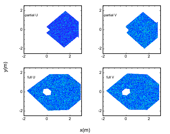
Figure 1a: Near Full and Partial Planes
I'm written some code that:
Scintillator plane geometry taken from the PDFs on the ND website. PDFs were read into xfig which was used to get the coordinates of corners, with a scale set according to the measurements visible on the figures. I estimate a 0.25-0.5 in. measurement error owing to this process. I'll take more accurate numbers if any are available.
There is one geometry for each PlaneView and PlaneCoverage in the near and far detectors, neglecting veto shield. No use is made of database information.
Randomly select points in the x,y plane. Plot those inside the scintillator.
Figure 1a: Near Full and Partial Planes

Figure 1b: Far Planes
For a grid of points in the x,y plane compute the distance to the nearest edge.

Figure 2a: Near Full and Partial Planes: color represents distance from bin to nearest edge.

Figure 2b: Far Planes: color represents distance from bin to nearest edge.
Get in the "plane of the plane". Compute the amount of plane along X,Y,U and V lines of sight.
These could maybe be added, in black and white, to an event display (like Mad's).

Figure 3a: Near Full and Partial Planes: color represents thickness of plane along view-line.

Figure 3b: Far Planes: color represents thickness of plane along view-line.
This code is written, validated and looking for a home. It's too small for it's own package. I wrote it to do fiducial and trace calculations in the near detector and to allow the tracker to figure out if an extrapolated track should have hit something. I also wrote it so that the active geometry could be shown in a web-page. But, I think it has a more general use and I'm a little resistant to placing it into CandTrackSR . Perhaps DataUtil or even Ugli ?
I can imagine various enhancements:
VldContext and plane or z position. Re: Brian's talk. Was this the plot I made?

Figure 4: True vertex position for events making it into the NtpMC ntuple.
Very well defined beam spread... a little fake looking?