 ZEUS Microvertex Detector Patch Box and Cabling Information at 24/11/2000
Janet Fraser - UCL. See also Oxford Pete Shield, Oxford Physics Central
Electronics Dept.and John Hill Oxford Physics Design Office.
Where do all the cables go? - Leo Wiggers web pages
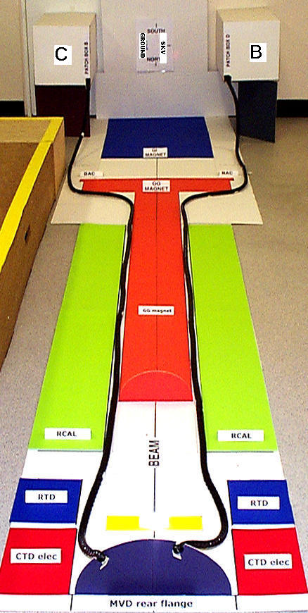
Cable Entry and Clamping Scheme for Patch Boxes
Pete Shield's diagram of how cables will fit into the patch boxes (25.04.2000)
- Here is a list of CABLES from the MVD
to the Patch box and from the Patch box to the crates in the Vetowall area
please let me know if there are any changes to this list - NEW - Here is a link to lists of cables to and from the HELIX Driver
- Here is a list of COMPONENTS for the Patch Box Modules
this list shows all components needed by Pete Shield - please send info where needed!
RJ45 connector diagram
RJ45 connector cabling - signals list
29th November 2000 - this is now with latest RCAL - GG dimensions . Note that the triangular iron sections are still 60x60mm from the corners of the RCAL gap
Here is an update of the drawing of the GG/RCAL area with Combo cables in 'zipper tube' of the type now being used for combo cable bunching at NIKHEF.
The dimensions of the bunches containing 5 Combo cables wrapped in 'zipper tube' are 26mm x 5mm approx.
This can be compared with the previous type which measured 26mm x 8mm .
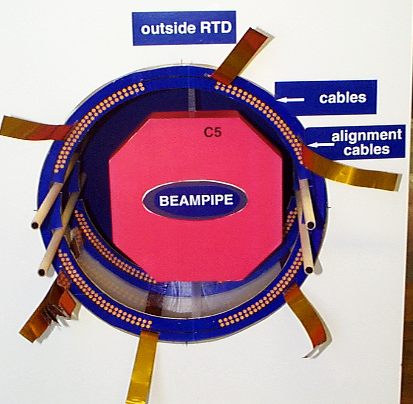
The difference is due to the absence of the plastic zip and its covering, together with a braid which is less thick. An adhesive strip replaces the zip. The combo cables will need to be flat within the tube in order for the bunches to fit in the restricted areas around GG magnet/RCAL and in the C5 area.
5th June 2000
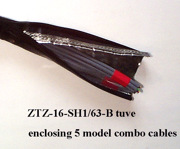
A 4 meter length sample from ZIPPER-TECHNIK - ZTZ-16-SH1/63-B tube was tested at UCL.
5 model combo cables were enclosed on the tube (using the tip of a ball-point pen as the special tool was not available!!).
First observations:
The inside diameter of the tube is 16mm so a bunched set of 5 cables
fits easily with room to spare but the outside
diameter of the tube is
20 x 18mm. The zip edge and the shielding braid causes the extra width,
ie 20mm. Here is a photo of the end of the zipper tube.
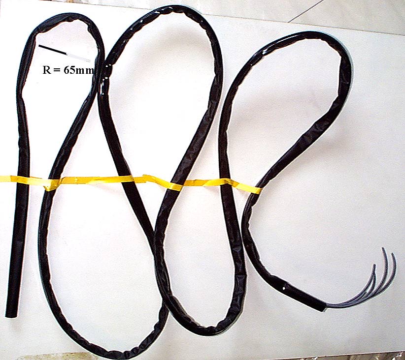
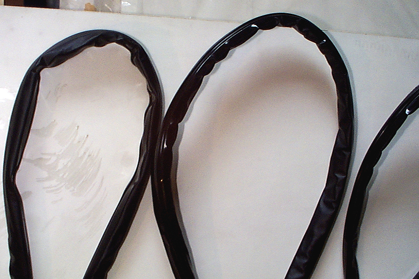
The tube is fairly stiff and bending is easier with the zipper edge on the
outside of the bend. A bend radius of 30mm is possible if forced but a radius
of 65 would be the safest maximum. See photo of cable
with bends.
Unfortunately the tube becomes buckled when bent, so the precise diameter
cannot be maintained, thus much more space is occupied on bends. Note variation in diameter.
CONCLUSIONS:
see below for latest drawing
(15.06.2000)
GOOD: zippertube is strong and unlikely to come apart even when bent over
a radius of 65mm. Although stiff, it can be bent through the necessary radii
en-route from MVD to patch boxes.
BAD: zippertube enclosing 5 combo type cables occupies much more space than
formerly allocated. If the 5 cables are placed in a row inside the tube then the flat profile takes up 10 x 25mm (the zip and enclosed braid causing the extra thickness). The new profiles of cable bunches enclosed in zippertube have
been added to the drawing of the combo cables in the
GG magnet area.(see the yellow rectangle and circle top left). There are no very sharp bends on the combo cable route but there will be some buckling due to changes in direction so packing factor will vary en-route
.
Obviously the tube can be 'squashed' to a certain extent as cables do not
fill it, but the extra material takes up a lot of space. On the other hand, if a smaller diameter version of the same tube type was available, enclosing the cable tightly would make it less flexible.
The cable bunches become heavier and will need a very strong 'cage' to keep
them in place away from the C5 detector.
07.06.2000 update:
If zippertube is squashed flat, with cables carefully laid flat inside it
it is posssible that several cables could be laid in layers to take up marginally less space. Here is a sketch of the flattened zippertube.Note that this can only work in straight sections where cable does not
have to bend.
09.06.2000
Here is the drawing of the cable route through the RCAL/GGmagnet space, modified to give an idea of how the combo cables enclosed in this type of zippertube
would fit in, (section at top) compared with former arrangement (section
at bottom).Note how space is filled completely!. Also note that the zippertube is squashed flat and would have to be held in position
with a very strong 'cage' in order to keep the 'low profile'!
15.06.2000
This is the latest drawing of cables bundled in zippertube showing at top - tube squashed flat and at bottom - round tube 19mm diameter - same tube not squashed flat.
NOTE that this does not fit in the space available.
Comments/Verdict from Pete Shield re zippertube impact on Patch Box entry and from John Hill and Brian Payne re impact on installation will appear here as soon as they are received.
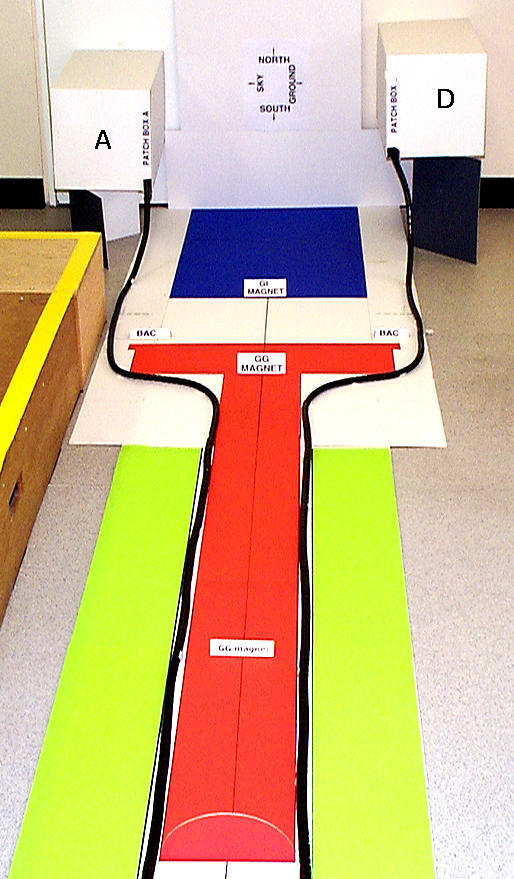
please note change to patch box names
- as viewed looking into the interaction region, they are from top left going clockwise ABCD