File list
Jump to navigation
Jump to search
This special page shows all uploaded files.
| Date | Name | Thumbnail | Size | User | Description | Versions |
|---|---|---|---|---|---|---|
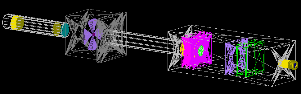
| 04:00, 1 April 2021 | F TOPASbeamline.png (file) |  |
47 KB | JacintaYap | CCC beamline TOPAS visualisation | 1 |
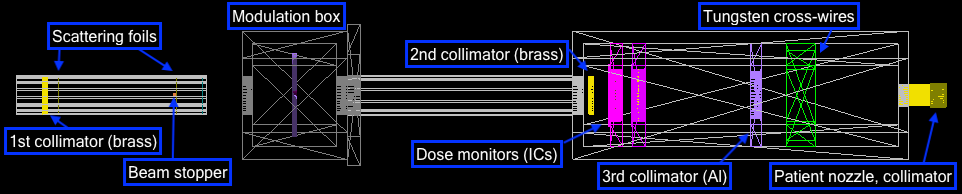
| 04:03, 1 April 2021 | F TOPAS topview labelled.png (file) | 42 KB | JacintaYap | Beamline birds eye view, major components labelled | 1 | |
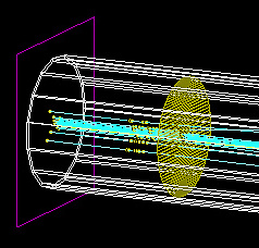
| 05:53, 1 April 2021 | F TOPAS source tube run.jpg (file) |  |
41 KB | JacintaYap | Particle beam origin at source plane and start of scattering tube | 1 |
| 06:12, 1 April 2021 | F TOPAS scoringinphantom.png (file) |  |
49 KB | JacintaYap | Dose deposition in a 40x40x40mm^3 water phantom | 1 |
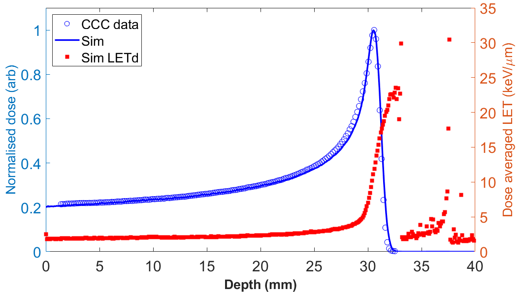
| 04:42, 1 April 2021 | F TOPAS matchBP.png (file) |  |
79 KB | JacintaYap | Matched Bragg peak and LETd curve scored in a water phantom. | 1 |
| 05:30, 1 April 2021 | F TOPAS film beamline.png (file) | 27 KB | JacintaYap | Scoring within EBT3 film volumes for transverse beam distributions | 1 | |
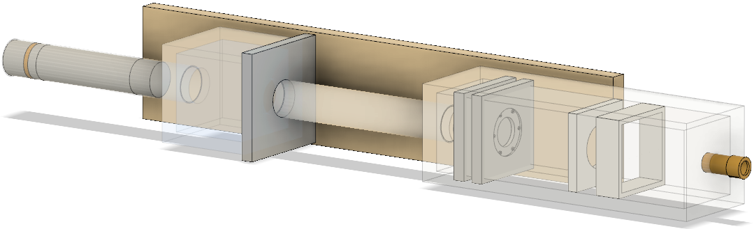
| 04:02, 1 April 2021 | F CAD treatmentline.png (file) |  |
137 KB | JacintaYap | Treatment line in CAD | 1 |
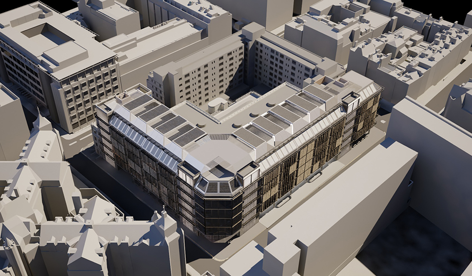
| 12:16, 24 March 2016 | EWA UCLH4 06.jpg (file) |  |
441 KB | SimonJolly | Overhead rendering of UCLH Proton Beam Therapy centre. Reproduced courtesy of Edward Williams Architects: http://www.edwardwilliamsarchitects.com/projects/view/uclh-phase-4-and-proton-beam-therapy-unit-london-uk | 1 |
| 16:15, 14 July 2017 | Dosimetry box.pdf (file) | 874 KB | MatthieuHentz | Annotated PDF of the components along with their positions in the dosimetry box. | 1 | |
| 16:05, 6 July 2017 | Dose monitor exploded.png (file) |  |
59 KB | MatthieuHentz | An exploded view of a dose monitor as used in the dosimetry box. It consists of a set of aluminised mylar foils wedged between layers of perspex to hold them in place. The guard ring is used to create a sealed volume of air between the foils. The aluminium layers face towards the centre of the dose monitor such that the assembly acts as a drift chamber when a potential difference is applied. | 1 |
| 16:18, 14 July 2017 | Dose monitor doc.pdf (file) | 48 KB | MatthieuHentz | Annotated PDF of the position of components in the dose monitors. | 1 | |
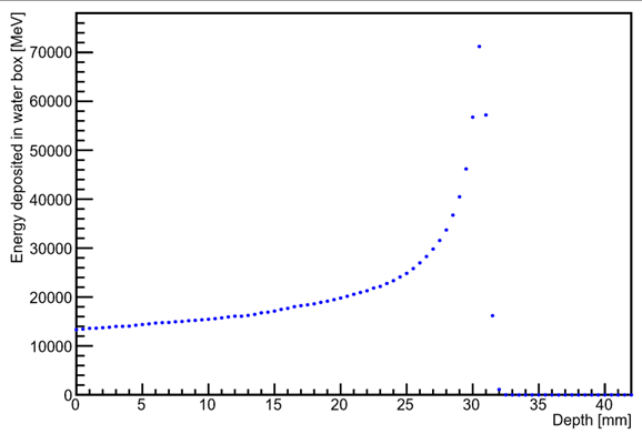
| 20:00, 30 August 2016 | Cumulative energy deposition in water.png (file) |  |
32 KB | RoisinStephens | 1 | |
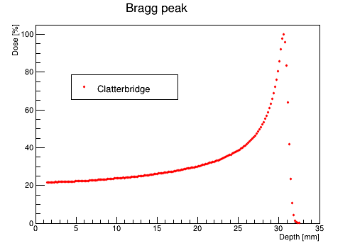
| 18:44, 31 March 2016 | ClatterbridgeBraggPeak.png (file) |  |
7 KB | SimonJolly | 1 | |
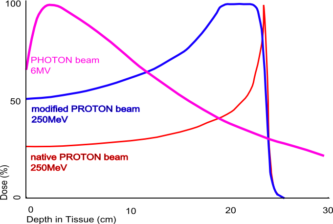
| 12:05, 24 March 2016 | BraggPeakWikipedia.png (file) |  |
47 KB | SimonJolly | Bragg Peak image downloaded from https://en.wikipedia.org/wiki/Bragg_peak. | 1 |
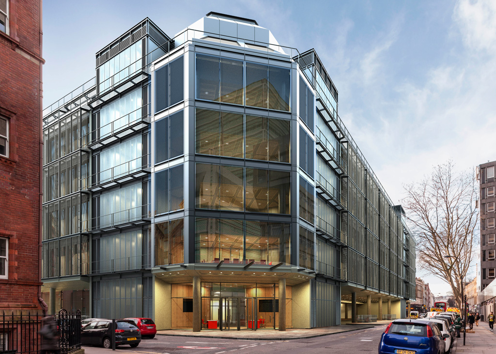
| 15:56, 24 March 2016 | Bouygues UCLH4 Phase-4-PBT-Entrance-small.jpg (file) |  |
360 KB | SimonJolly | Public entrance to UCLH Proton Beam Therapy facility on the corner of Grafton Way and Huntley Street. | 1 |
| 12:24, 6 July 2017 | Beamline top down.png (file) | 119 KB | MatthieuHentz | A top-down view of the beamline showing all its components: (a) first aluminium tube, (b) first aluminium box, (c) iron block, (d) second aluminium tube, (e) second aluminium box (dosimetry box), (f) shielding made of borated plastic, (g) brass nozzle, (h) water volume. | 1 | |
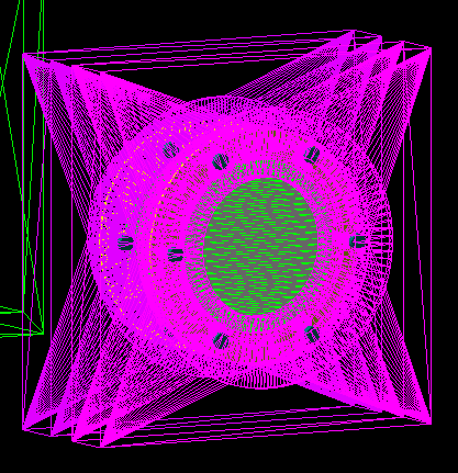
| 13:00, 6 July 2017 | Beamline perspective.png (file) |  |
342 KB | MatthieuHentz | Cropped the image | 3 |
| 23:58, 9 July 2017 | Beamline doc.pdf (file) | 1.59 MB | MatthieuHentz | Schematic of the beamline showing all its components and their positions relative to the source. | 1 | |
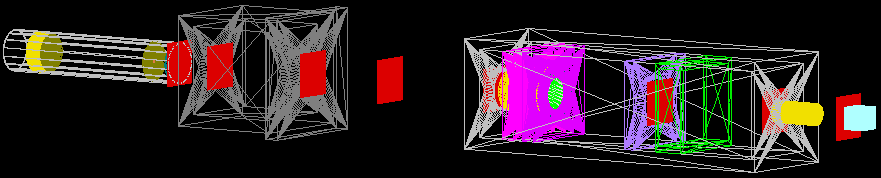
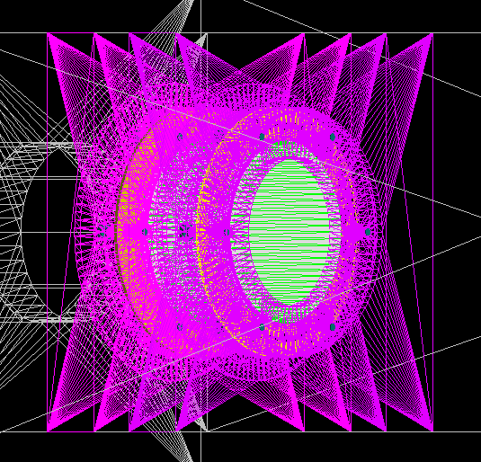
| 16:29, 6 July 2017 | Beamline 500 sim perspective.png (file) |  |
1,014 KB | MatthieuHentz | Beamline visualised in DAWN v3.90b. The first tube and second box are visualised using the wireframe setting so that their inner components are visible. This simulation contains 500 primary protons. Protons are shown in blue, electrons are red, positrons are cyan, gamma rays are green, neutrons are yellow. | 1 |
| 15:53, 5 July 2017 | Background-sources-of-radiation.png (file) |  |
17 KB | SimonJolly | Natural sources of radiation. Originally obtained from: http://www.world-nuclear.org/information-library/safety-and-security/radiation-and-health/nuclear-radiation-and-health-effects.aspx (05/07/2017). | 1 |
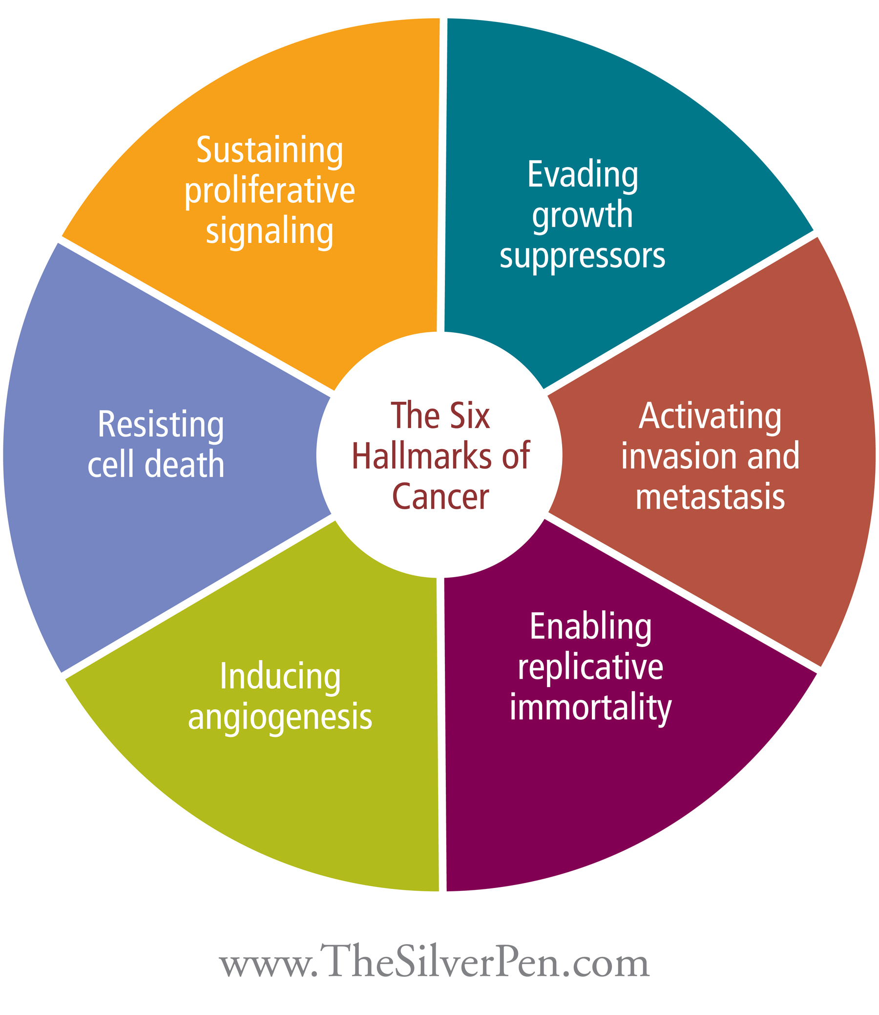
| 13:38, 4 July 2017 | Background-hallmarks-of-cancer.jpg (file) |  |
813 KB | SimonJolly | The six hallmarks of cancer. Originally downloaded from: http://www.thesilverpen.com/wp-content/uploads/2012/09/hallmarks-of-cancer.jpg Originally published at: http://www.thesilverpen.com/breast-cancer-information-facts/hallmarks-of-cancer/ Originally described in: Hanahan D, Weinberg RA. The Hallmarks of Cancer. Cell 2000;100:57–70. doi:10.1016/S0092-8674(00)81683-9 | 1 |
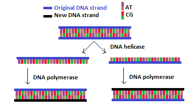
| 15:31, 4 July 2017 | Background-DNA-replication.png (file) |  |
6 KB | SimonJolly | DNA replication | 1 |
| 06:01, 1 April 2021 | A dosemonitorsF.png (file) |  |
94 KB | JacintaYap | Dose monitors, front view | 1 |
| 06:02, 1 April 2021 | A dosemonitorsB.png (file) |  |
60 KB | JacintaYap | Dose monitors, back view | 1 |
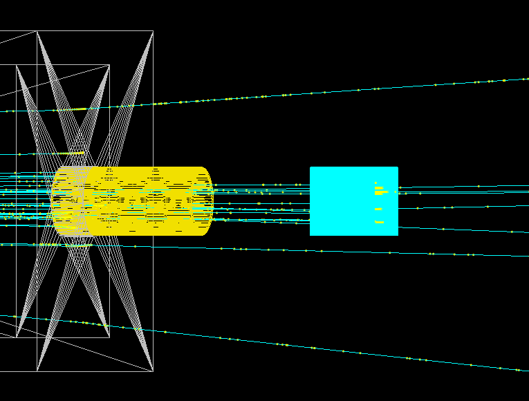
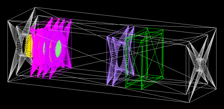
| 06:00, 1 April 2021 | A TOPAS nozzle.png (file) |  |
42 KB | JacintaYap | Nozzle and phantom | 1 |
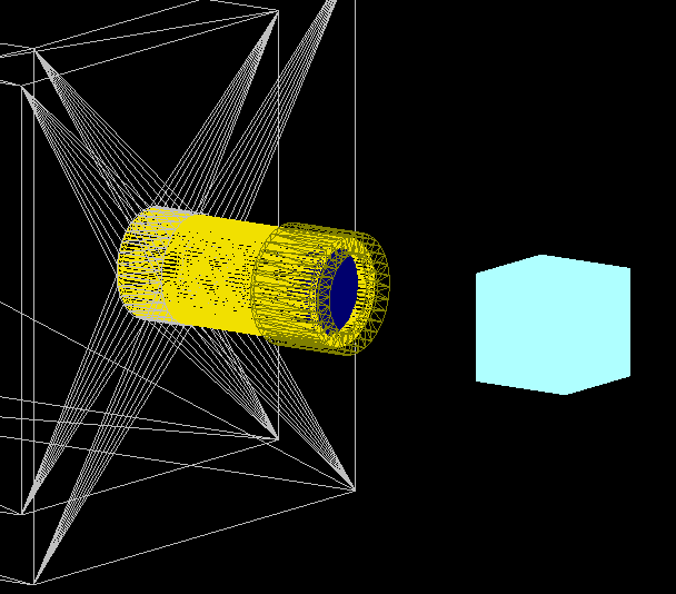
| 05:58, 1 April 2021 | A TOPAS ScatteringTube collimator.png (file) |  |
23 KB | JacintaYap | Scattering tube with double tungsten foils | 1 |
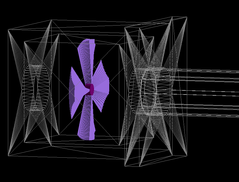
| 05:59, 1 April 2021 | A TOPAS ModBox.png (file) |  |
68 KB | JacintaYap | Modulation box, rotating wheel | 1 |
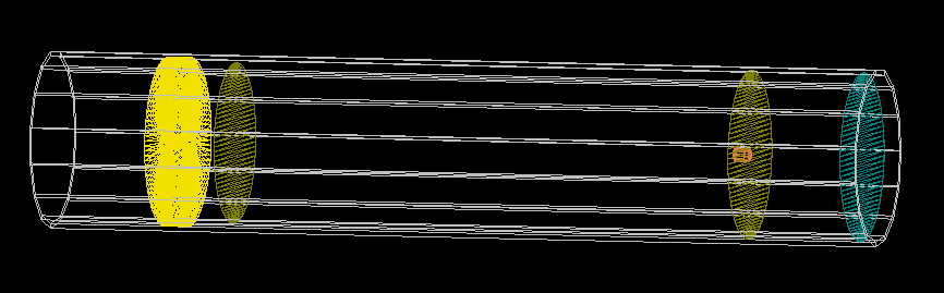
| 05:59, 1 April 2021 | A TOPAS Dosimetrybox.png (file) |  |
48 KB | JacintaYap | Dosimetry box | 1 |
| 04:14, 1 April 2021 | A CCC treatmentline drawing.pdf (file) | 116 KB | JacintaYap | Schematic of all component dimensions, generated from Autodesk fusion | 1 | |
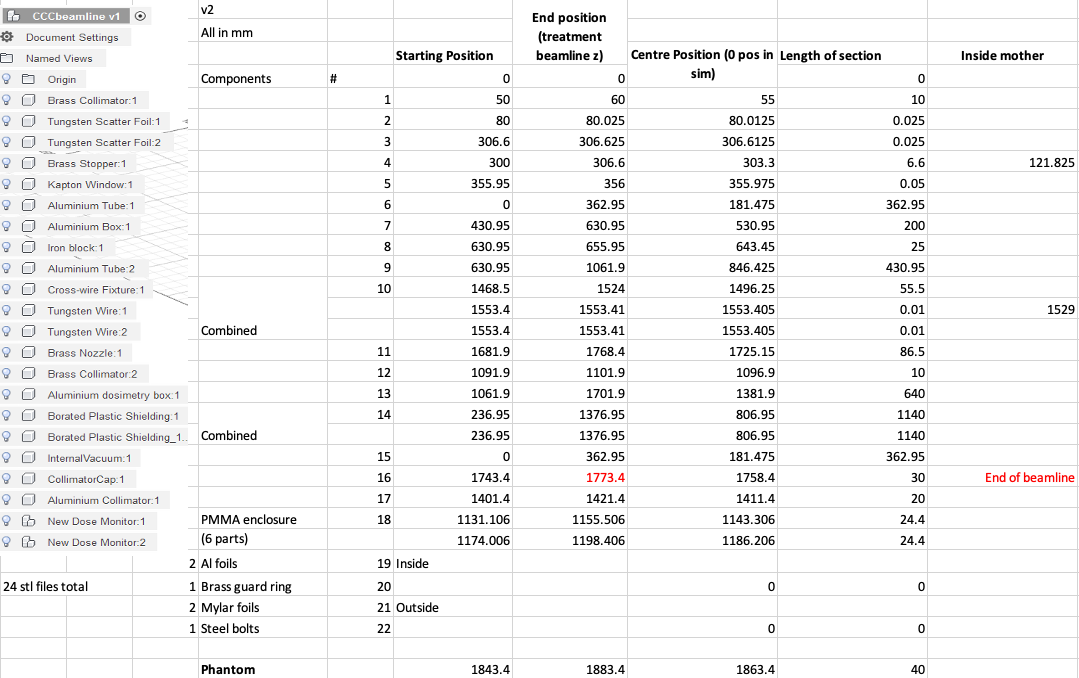
| 04:33, 1 April 2021 | A CCC dim spreadsheet topas.png (file) |  |
182 KB | JacintaYap | Component positions in TOPAS relative to treatment line coordinates | 2 |