PIN FIBRE INSTALATION
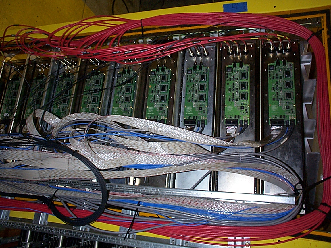
This is one MUX box rack on the upper level. You can make out a black fibre bundle which connects at one end to the PIN connectors on a pulser box and on the other (as can be seen in this photo) to the PIN diodes on the electronics front end boards on the MUX boxes.
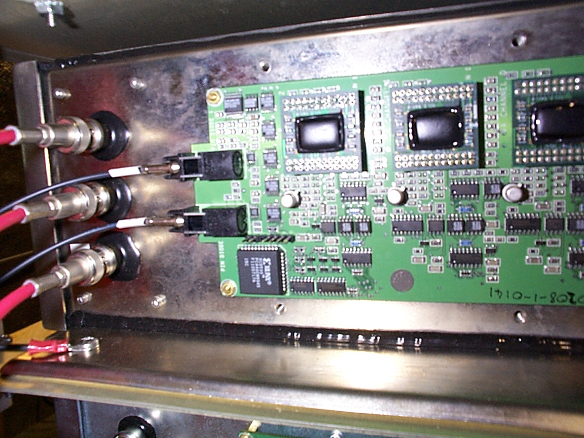
A close of of the PIN fibre installation. Note that the fibres need to be routed carefully at the vfb end as spare is limited. The upper PIN diode in this shot is PIN 1 and is high gain .
TRIGGER FIBRE INSTALLATION
The trigger PMT sits in a special MUX box that is to be situated under eight other MUX boxes in the most southwesterly top-level rack. It is to use the spare HV cable supplied to that rack, and readout will be to a spare channel in the VARC just as with any other MUX box (Crate 1, VARC 2, VMM 5, VAADC 0, VACHIP 1). The high voltage to this MUX box must be off during installation of ANY trigger PMT fibre, which is a part of the installation of a pulser box.
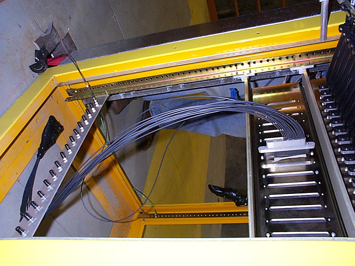
The optical connection to this MUX box has 16 fibres that terminate in SMA connections. These connectors should be fixed to the rear of a rack-mounted patch panel below the MUX box. Before a pulser box is installed, the fibre ends are not put into the patch panel because of the possiblilty of light leaks. Instead the unused fibres are wrapped together in a light tight bag which sits at the bottom of the rack, (the patch panel is more difficult to light tight).
There are sixteen fibres, each 50 m in length: one for each pulser box. Spare fibre should coil up at the bottom of this same rack or in a safe place in one of the cable trays. One end of each of these fibres attaches to the patch panel; the other end attaches to the SMA connector situated adjacent to the mains lead on each pulser box.
An attenuator (which could be, e.g., a piece of paper cut to size) should be inserted between the two halves of the connector at the MUX box as the light from the trigger LED is extremely bright, and may cause premature deterioration of the M16 photocathode. In addition the trigger PMT should be run at a low voltage. Currently a thin piece of lens cleaning paper is between the connectors at the MUX box and the HV is being run at 500V.
To find out which vachannel corresponds to each pulser box, either look at a LI data file or look at the plex for the trigger MUX box.
This is the trigger MUX box. The 16-way patch panel at the bottom connects the individual trigger fibres from each of the pulser boxes to one of the 16 fibres from the 30-way MUX connector. At the MUX box connection, sheets of lens cleaning paper were inserted to reduce the intensity of light reaching the M16 phototube.
Back to main LI installation page