PPB1 LMT board assembly on PPB1 support board
photos J.Fraser 11th November 2003
photos of a trial assembly of the PPB1 LMT boards on the support board
(click for a larger view)
FRONT position clamp - holds cables firmly but note
that at this stage no ferrules were used as the trial cables
already had crimped connectors.
It was not possible to get the ferrule along from the
other end of the cable.
Photos of a separate trial with FERRULES fitted to the cables
can be found towards the end of this page

Although the 6 cables fit in the FRONT clamp,
they are very squashed between the square spacers located over screws.
It was not possible to get 6 between the spacers further along -
bulges in the cable and it's solid nature prevented squeezing out of shape.

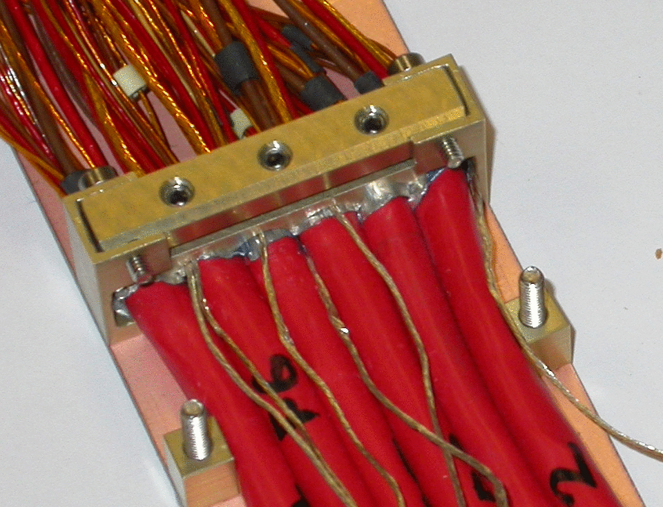
Detail of FRONT cables under the REAR board
Note that it was not possible to screw the PPB1 board down fully
onto the spacers probably due to the slope of the cables
and the screw base section under the PPB1 (see also in next photo)

Detail of FRONT cables under REAR board viewed from above

5 cables fit well between square spacers,
the sixth cable had to be left out.
The REAR strain-relief clamp is partly assembled

View from above. As spacers are 6mm high they do not act as
strain-relief for the FRONT cables

Another view of the clamp

LMTs going under strain-relief of REAR board -
note chamfer on the edge of the cable clamp

detail of LMTs from the side

View of REAR clamps with REAL cable strain-relief in the centre.
The FRONT cables running underneath are NOT strain-relieved here.
The single lower (FRONT) clamp on the left and the
double (FRONT and REAR) clamp on the right do not provide strain-relief.
Trials with ferrules fitted to cables

Close-up of drain wire soldered to a ferrule
fitted over a TYPE II cable
Note that the wire strands are separated out and flattened
before soldering
Would the wire be soldered to the ferrule somehow before
it is fitted over the red sleeving? (as heat may melt sleeving)

6 cables with ferrules and soldered drain wires

6 cables with ferrules installed on the support board
ready for clamping

The profiled section of the clamp is fitted over the ferrules

The top section of the clamped is fixed using screws
to push down onto the profiled section to clamp the ferrules
Note that the gap between top and middle sections is 2mm
( about 1mm wider than on the clamp in the trial with cables
without ferrules). It was necessary to tighten the clamp to this extent
in order to prevent the ferrules/cables from slipping out of the clamp -
which happened if cables were gently pulled.
Note the bend in the sides of the clamp

View of the clamp showing distortion caused by having to
over-tighten the screws