ZEUS MVD Clock and Control
The HELIX Driver and Patch-Box PSU's Control and Monitoring System:
System Overview:
C+C off-detector power is derived from 2 power supply units:
- Patch-Box PSU (PB PSU): Powers the C+C LVDS/CMOS circuitry in the Patch-Boxes
- HELIX Driver PSU (HD PSU): Powers the LVDS transmitters on the HELIX Driver boards as an attachment at the rear of an adapted VME crate.
Each of these supplies is fitted with remote control and monitoring. From the remote end, these units can be seen as identical, save for the number of channels involved. Each PSU is made up of 'modules' - a distinct unit in the box providing two output voltages. One of these outputs is often tied to a 0V level (and therefore not monitored). Each module is assigned a channel with an ID. 0 for module 1, 1 for Module 2 etc. Channel data provides all known information regarding one module (voltages, currents and temperature)
Communication is via 3 wire RS232, using an 8-byte wide 'message' protocol. A separate RS232 port is used by each PSU. In addition to channel-by-channel readout, the controller also provides on/off status, error/trip and reset status. Each PSU can be shut-down/started remotely, although this is dependent upon on the relevant interlocks being true (see the Interlock section later). The Controller is powered using it's own on-board power-supply directly from the each PSU's physically switched mains power. After mains switch turn-on, the PSU will remain in an 'off' state (i.e. the DC outputs are floating/0) until told otherwise.
Each PSU is also provided with a controller override system: A momentary 2 pole toggle switch is used to power up the system regardless of the Controller's condition ('controller override' or 'controller disable'). The opposite direction of the switch provides the reverse: 'cancel override' or 'enable Controller'. This can be used as a 'softer' power-down (assuming the controller is not setting the PSU on itself). This override is completely auxiliary to the controller system, and is implemented in as simple and failsafe electronics as possible (positive logic, pull-downs and a single F-TTL chip only). It derives its power from the VME crate 5V (i.e. obeys the VME Interlock conditions).
|
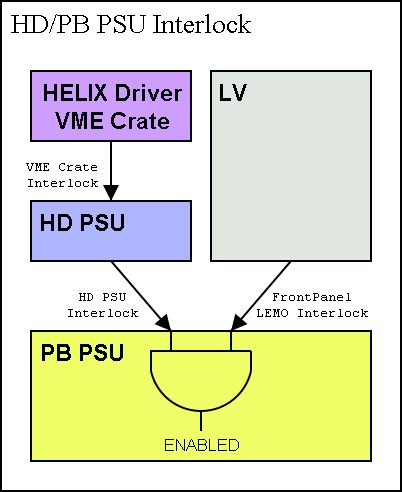
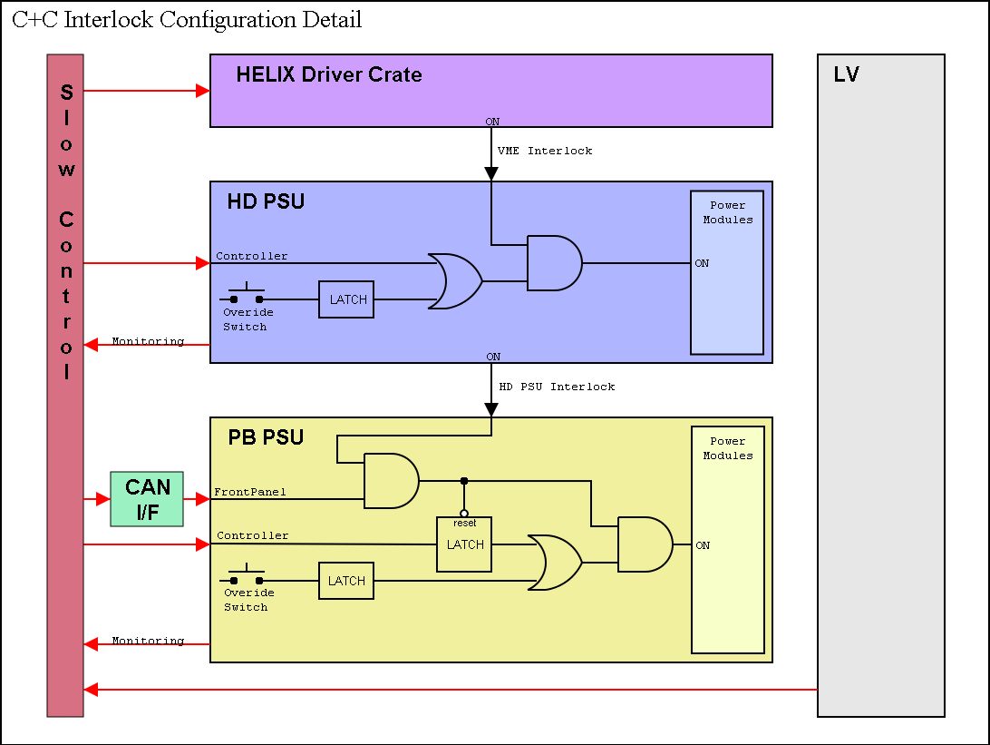
C+C PSU's Interlock
The PB cards can consume excess current when their LVDS inputs are incorrect/floating. This current can exceed the ratings of the PB PSU modules and it has therefore been important to implement an interlock between the 3 units involved in the C+C rack to PB system: In addition the PB PSU also depends on the LV being on.
|
|
Individual PSU Controller Operation:
The controllers are designed to be communication slaves to the remote (Slow Control) system. In this configuration we stipulate that the Controller will only send data when requested to by the SC. There are, however, two important exceptions:
- At start-up/reset the controller will issue an 'Operational' message. This message will provide information on the type of reset (power-up, button, remote) and the on/off status of interlock inputs and the Controller. [Note: The Controller and Override will be set the PSU OFF after a power-on reset]
- An 'Trip Condition' is noticed - that is a module's output voltage is below a predetermined level. In most cases the module itself will trip if an over-voltage condition occurs, and it's output voltage will then drop considerably, triggering an error - this message can therefore be thought of as a 'trip' message. Note: the entire PSU will be shut down by the controller if a trip occurs,So: Trip = PSU Auto-Shutdown. The most likely time for a trip is directly after the Controller is set ON. To avoid a 'comms-clash', the SC should not communicate with controller for a fixed period after the 'Status' message to allow time for the generation of an 'Trip' message (1s is sufficient).
Controller Program Cycle:
At reset, the controller will examine itself. If it finds that is has just been powered-up it will clear the PSU ON latch. (This latch is external to the controller's processor, as the processor pins can be unreliable at reset. Note that this latch has its own POR circuitry too). In any other case the processor will leave to PSU ON latch as is.
The code has been designed to be able to loop from a complete reset each cycle if needed. This has an important implication: a RESET will NOT INTERFERE WITH THE PSU ON/OFF CONDITION.
- After a reset, an 'Operational' message is sent.
- Next, the A/D channels are read and the values run through the error/trip detect functions. If the error is found to persist, an 'Error' message is sent and the PSU is set OFF.
- The Serial Receive buffer is then checked and, if full, acted upon (actual Serial RX is performed by an interrupt handler and therefor auxiliary to the main program loop)
- Then the cycle repeats.
Communications Messaging:
Communications between the SC and the Controller is carried out using 8 byte long messages. Byte 0 of each message contains the message opcode/id. Via the opcodes the SC can request information on a channel by channel basis, ask for overall status, set the PSU on or off etc. The controller replies to all requests by default. These replies (in most cases) have the same opcode in byte-0 and any requested information in remaining 7 bytes.
Replies to SC requests are immediate, except after the following
- A PSU on/off request (opcode 0x41, 0x40): A short delay (~500ms) will precede the on/off reply as the modules themselves will require time to comply. This also facilitates Trip/Error detection.
- After a software-reset request: The normal reset cycle delay (1s) will precede an 'Operation' message being sent (note: this will have a different opcode)
Messaging Handshaking:
The Controller and the remote SC system communicate with fixed length 8 byte messages. Fixed length affords a few advantages:
1) Less serial TX/RX subsystem overhead - system just needs to count bytes
2) Good error detection: the bytes are sent in quick succession - any delays will incur a timeout at the receiver - resulting in an aborted message and the byte counter reset.
During normal operation it is important that the SC system knows who is alive. (Note: The opposite direction is less important and the controller is able to act on any 'error' situation independently).
At start-up the controller will let the SC know it exists by sending an 'Operational' message. When the SC receives this is will be aware of a live system and 'watch' it at leisure (pole it for status etc. SLOWLY) If at any time the SC looses contact (i.e. a 'Status' request is ignored or an RX timeout occurs) it will try a number of times at increasing intervals to regain contact. If this fails, it will flag the controller failed and await its next 'Operational' message.
In the event of a 'comms clash' or some other anomaly, either the controller will experience a receive timeout and not respond to the SC, or the SC will experience the same. In both cases the SC will wait a short interval then retry/request status. This is felt to robust enough for the application.
[Note: The SC is NOT in any way responsible for first-line failure detection/trip activation.]
Message Definition:
Many messages reply with the Controller status after their opcode
|
Stat_Bytes: |
On_Off_Stat, Reset_Stat, Trip_Stat, 0, 0, 0, 0 |
|
On_Off_Stat |
|
|
bit 7-4: |
[unused] |
|
|
bit 3: |
Front panel on/off [if implemented] |
|
|
bit 1: |
interlock on/off |
|
|
bit 2: |
override on/off |
|
|
bit 0: |
controller on/off |
|
Reset_Stat |
|
|
bit 7-6: |
[unused] |
|
|
bit 5: |
[reserved - brown-out reset] |
|
|
bit 4: |
soft reset |
|
|
bit 2: |
[reserved - watchdog reset] |
|
|
bit 1: |
push-button reset |
|
|
bit 0: |
power-on reset |
|
Trip_Stat |
|
|
bit 7-5: |
[unused] |
|
|
bit 4: |
Test_trip |
|
|
bit 3: |
module 4 |
|
|
bit 2: |
module 3 |
|
|
bit 1: |
module 2 |
|
|
bit 0: |
module 1 |
|
UNSOLICITED: |
|
|
Operational: |
00, |
Stat_Bytes |
|
|
|
Error/Trip: |
80, |
Stat_Bytes |
|
|
|
|
NORMAL (REQuest, REPLy) |
|
|
Soft Reset: |
|
|
|
REQ: |
F0 |
|
|
|
|
|
REPL: |
(this will be the operation message after reset and may be slow to arrive) |
|
|
|
|
|
Module Status: |
|
|
|
REQ: |
1x |
|
|
|
|
|
x: |
0 = module 1 |
|
|
|
|
|
1 = module 2 etc. |
|
|
|
REPL: |
1x, V1, V2, I1, I2, LSBs, T, Spare |
|
|
|
|
|
V1,V2: |
Voltages (sense - i.e. at load) |
|
|
|
|
|
I1, I2: |
Voltages (output - i.e. at module terminals) |
|
|
|
|
|
LSBs: |
2 least significant bits of V1,V2,I1,I2 resp. |
|
|
|
|
|
T: |
Module Temperature |
|
|
|
|
|
Spare: |
|
|
|
PSU Status: |
|
|
|
REQ: |
20 |
|
|
|
|
REPL: |
20, |
Stat_Bytes |
|
|
|
|
|
Controller/PSU On/Off: |
|
|
|
REQ: |
4x |
|
|
|
|
|
x: |
0 = PSU OFF |
|
|
|
|
|
|
1 = PSU ON |
|
|
|
|
REPL: |
4x |
Stat_Bytes |
|
Patch Box PSU Calibration
|
Mapping: |
|
|
V1 |
V2 |
I1 |
I2 |
LSBs |
T |
Spare |
|
M1: 0x10: |
-5s |
- |
-5op |
- |
- |
- |
- |
|
M2: 0x11: |
+5s |
- |
+5op |
- |
- |
- |
- |
|
M3: 0x12:cont |
+2.1s |
-1.2s |
- |
- |
- |
- |
- |
|
M4: 0x13:clk |
+2.1s |
-1.2s |
- |
- |
- |
- |
- |
|
Calibration: [mV/bit] |
|
|
V1 |
V2 |
I1 |
I2 |
LSBs |
T |
Spare |
|
M1: 0x10: |
50 |
0 |
50 |
0 |
0 |
0 |
0 |
|
M2: 0x11: |
50 |
0 |
50 |
0 |
0 |
0 |
0 |
|
M3: 0x12:cont |
20 |
20 |
0 |
0 |
0 |
0 |
0 |
|
M4: 0x13:clk |
20 |
20 |
0 |
0 |
0 |
0 |
0 |
HELIX Driver PSU Calibration
|
Mapping: |
|
|
V1 |
V2 |
I1 |
I2 |
LSBs |
T |
Spare |
|
M1: 0x10: |
- |
- |
+3.8s |
-1.2s |
- |
- |
- |
|
M2: 0x11: |
- |
- |
-5s |
- |
- |
- |
- |
|
Calibration: [mV/bit] |
|
[mV/bit] |
V1 |
V2 |
I1 |
I2 |
LSBs |
T |
Spare |
|
M1: 0x10: |
0 |
0 |
50 |
20 |
0 |
0 |
0 |
|
M2: 0x11: |
0 |
0 |
50 |
0 |
0 |
0 |
0 |
Trips/Errors (***!!! NOT
IMPLEMENTED YET!!!*** Please Ignore)
To avoid accidental trips due to transients or A/D glitches, the system will only shut the PSU down after a number of program cycles have detected the condition. At present this is set to 255.
An 'error counter' (see the Error section) will be incrimented if an 'Error' is noticed. [If the errors have reached their max value the PSU is shutdown]
Test_Trip:
(this induces the normal trip reply)
REQ: 80
REPL: 80, Stat_Bytes
Trip Thresholds:
M1: -5.0 = -2.0: 1.2V = -3V
M2: +5.0 = +2.0: 1.2V = +3V
M3: +2.1 : 1.2V
M4: +2.1 : 1.2V
Trip Thresholds:
M1: +3.8 = +1.5: +1.2V = +3V
M2: -5.0 = -2.0: -1.2V = -3V