Uploads by MatthieuHentz
Jump to navigation
Jump to search
This special page shows all uploaded files.
| Date | Name | Thumbnail | Size | Description | Versions |
|---|---|---|---|---|---|
| 16:18, 14 July 2017 | Dose monitor doc.pdf (file) | 48 KB | Annotated PDF of the position of components in the dose monitors. | 1 | |
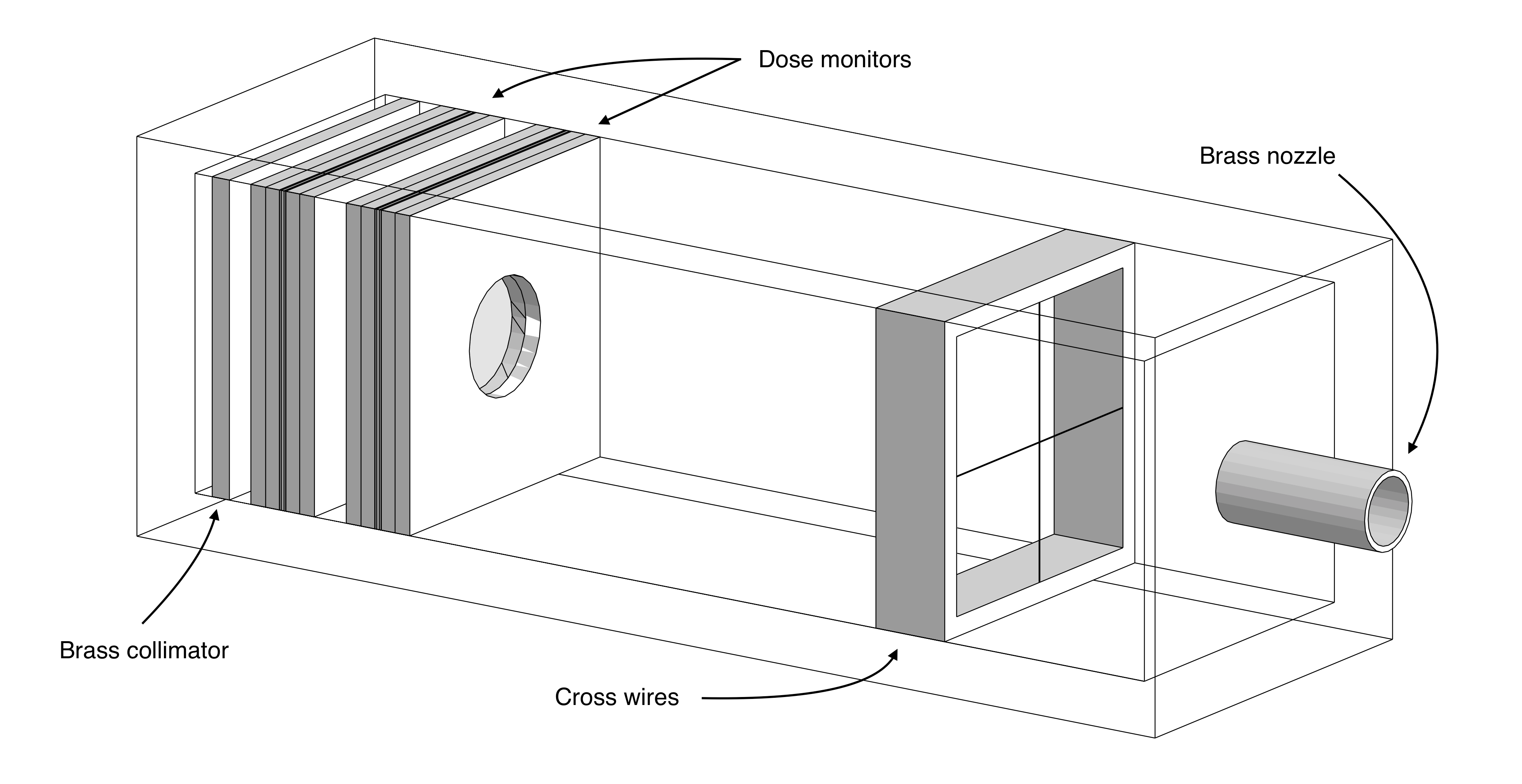
| 16:15, 14 July 2017 | Dosimetry box.pdf (file) | 874 KB | Annotated PDF of the components along with their positions in the dosimetry box. | 1 | |
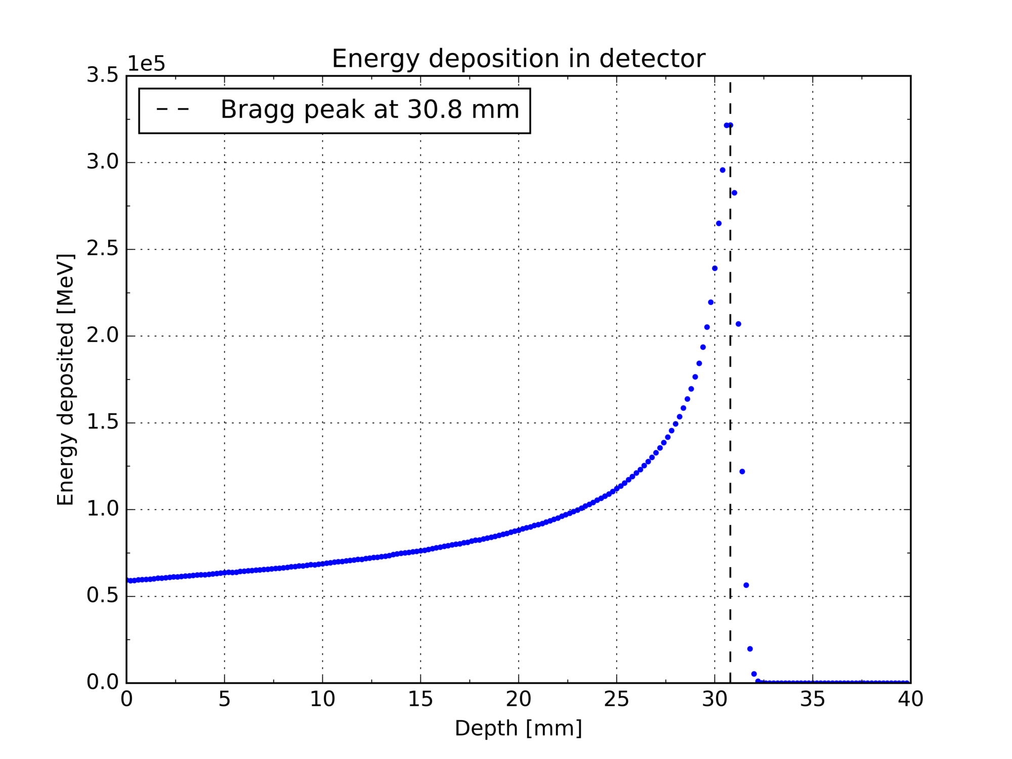
| 17:23, 10 July 2017 | Lon energy deposition bragg.png (file) |  |
190 KB | Longitudinal energy deposition profile in the detector showing a pronounced Bragg peak at 30.8 mm. | 1 |
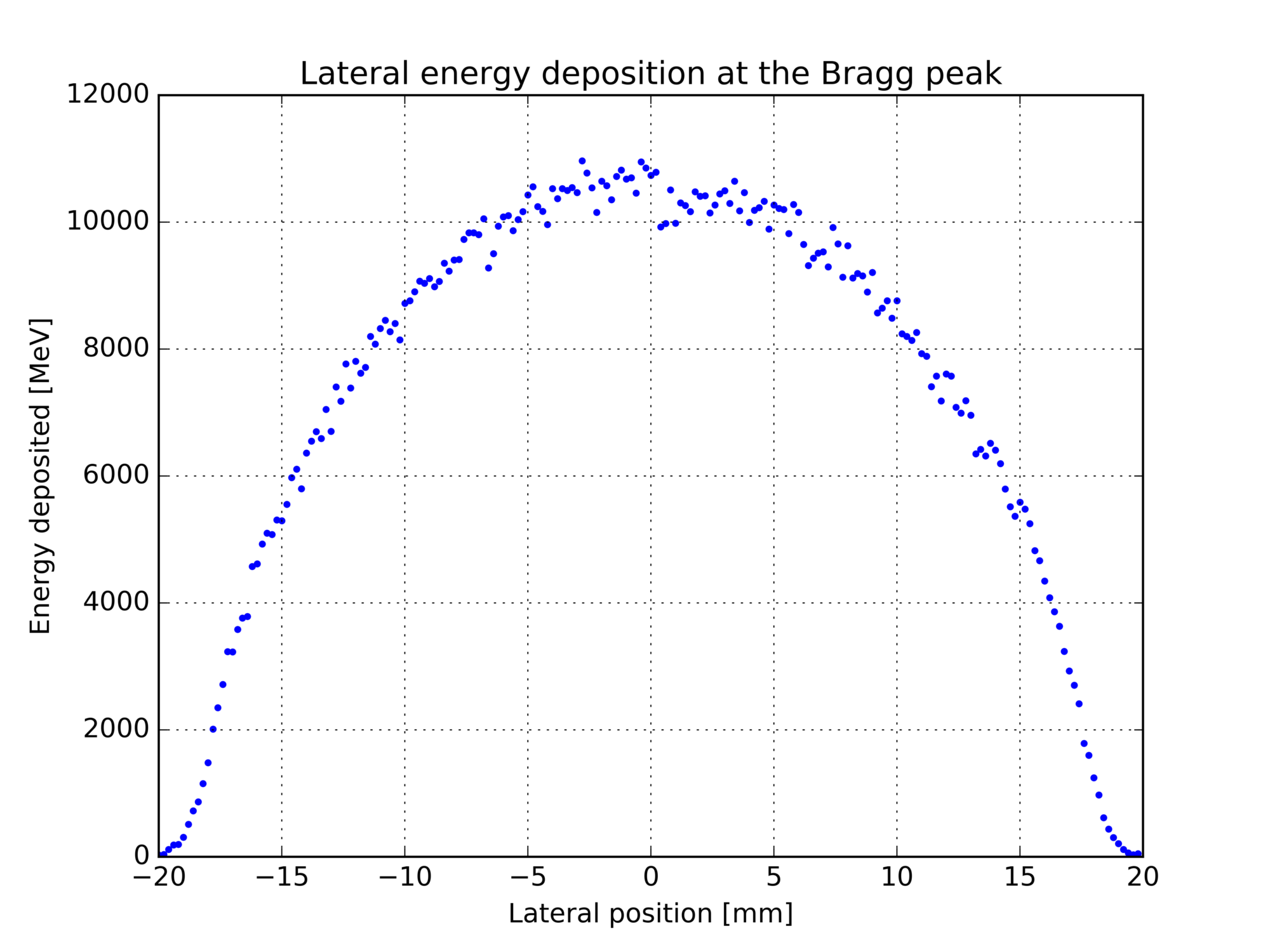
| 13:28, 10 July 2017 | Lat energy deposition bragg.png (file) |  |
219 KB | Adjusted dimensions | 2 |
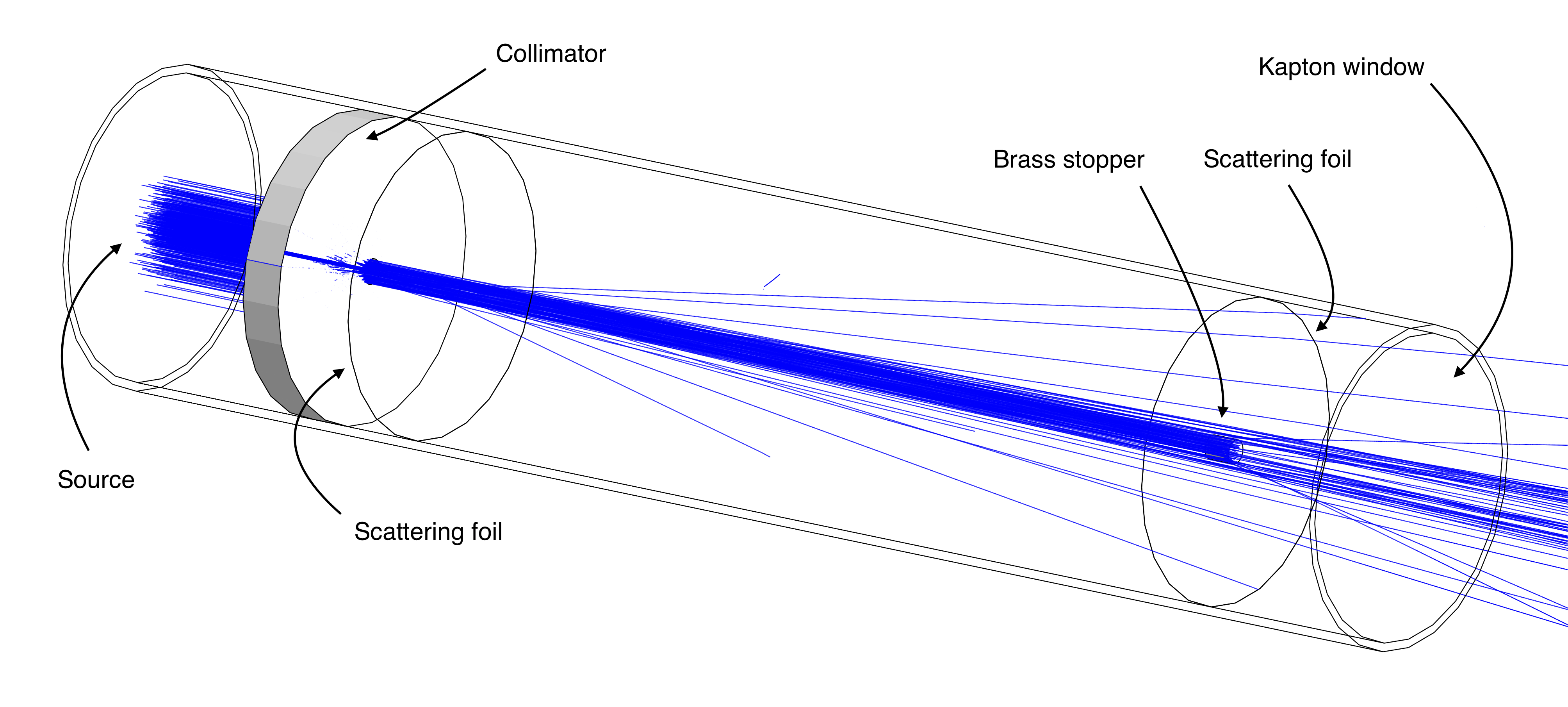
| 00:09, 10 July 2017 | Tube doc.pdf (file) | 700 KB | Annotated schematics of the dual scattering tube. | 1 | |
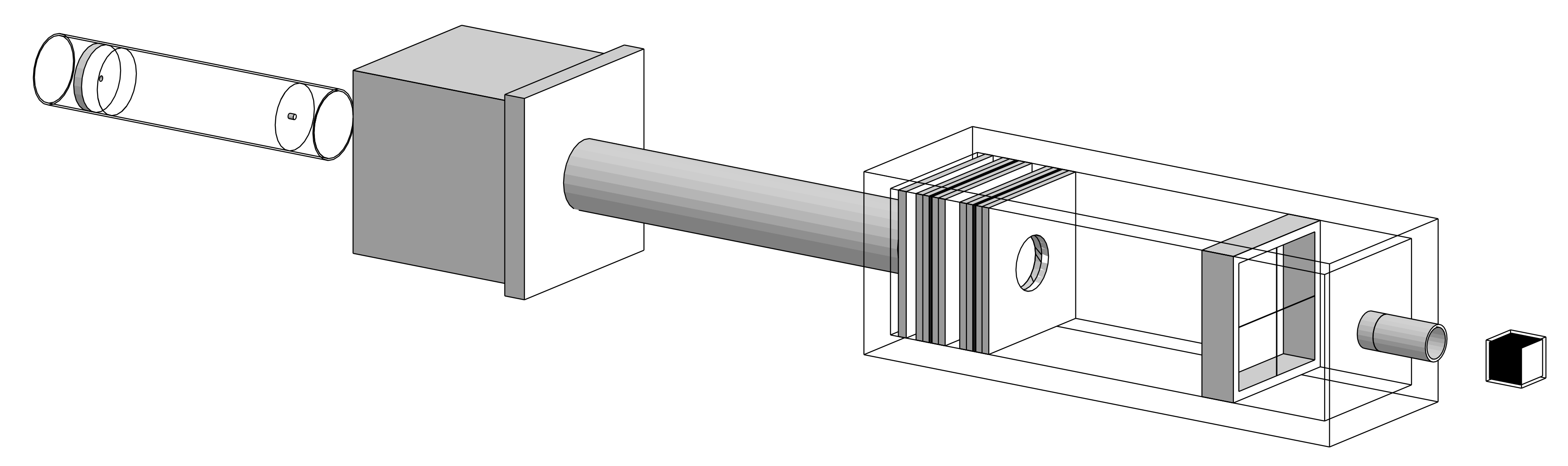
| 23:58, 9 July 2017 | Beamline doc.pdf (file) | 1.59 MB | Schematic of the beamline showing all its components and their positions relative to the source. | 1 | |
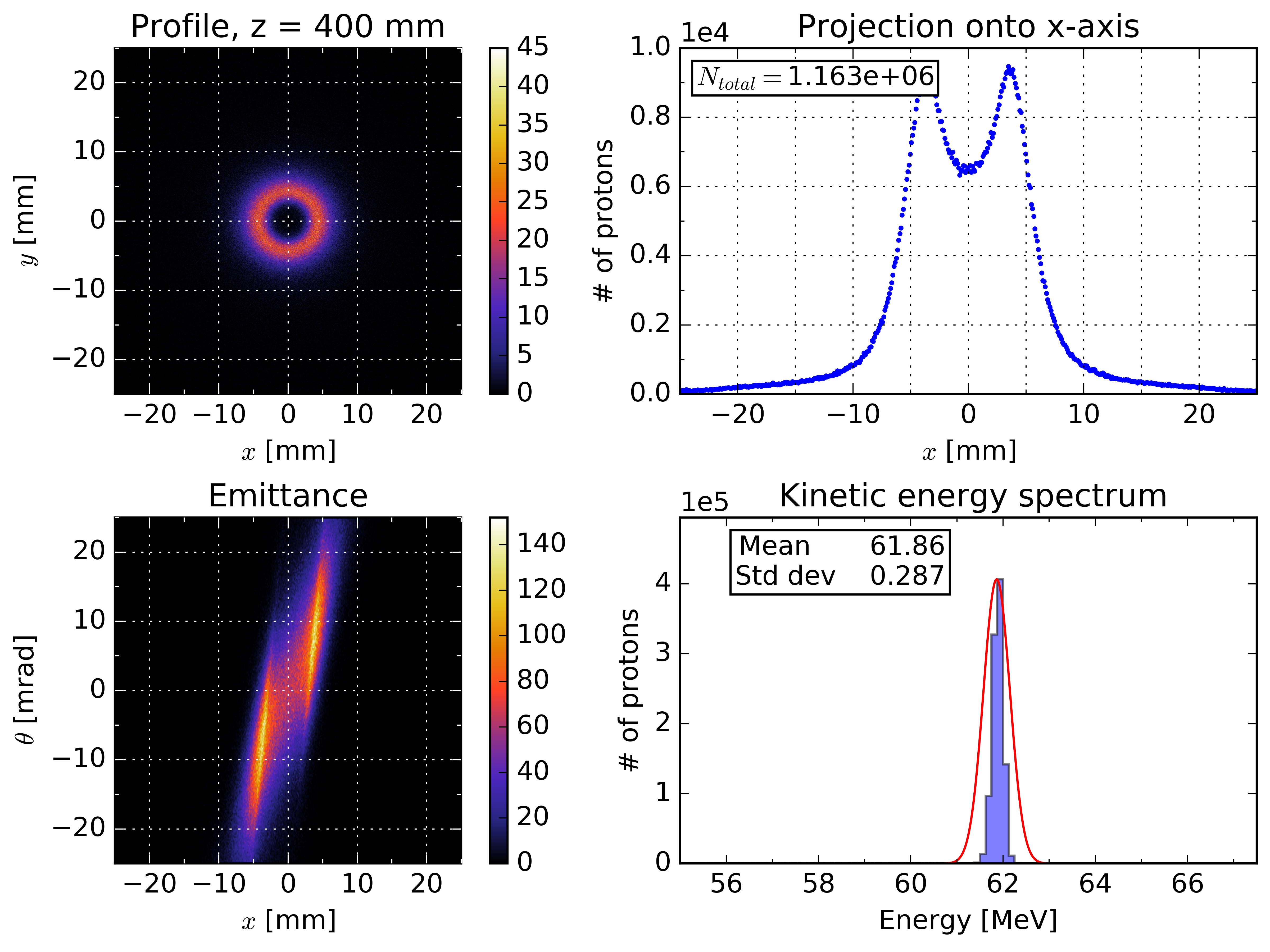
| 19:50, 9 July 2017 | Tiles 400.jpg (file) |  |
1.89 MB | Beam profile, projection of profile onto x-axis, emittance and energy spectrum 400 mm along the beamline. | 1 |
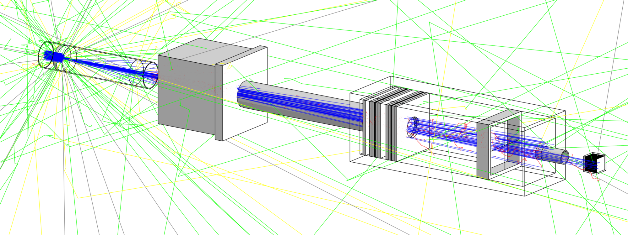
| 16:29, 6 July 2017 | Beamline 500 sim perspective.png (file) |  |
1,014 KB | Beamline visualised in DAWN v3.90b. The first tube and second box are visualised using the wireframe setting so that their inner components are visible. This simulation contains 500 primary protons. Protons are shown in blue, electrons are red, positrons are cyan, gamma rays are green, neutrons are yellow. | 1 |
| 16:05, 6 July 2017 | Dose monitor exploded.png (file) |  |
59 KB | An exploded view of a dose monitor as used in the dosimetry box. It consists of a set of aluminised mylar foils wedged between layers of perspex to hold them in place. The guard ring is used to create a sealed volume of air between the foils. The aluminium layers face towards the centre of the dose monitor such that the assembly acts as a drift chamber when a potential difference is applied. | 1 |
| 15:53, 6 July 2017 | Second box.png (file) |  |
634 KB | A visualisation of the dosimetry box. The box is made of aluminium and contains a brass collimator, two dose monitors and cross wires. The brass nozzle is fixed to the end of the box. | 1 |
| 15:28, 6 July 2017 | First tube 500 sim.png (file) |  |
1.19 MB | Increased font size of annotations | 3 |
| 13:00, 6 July 2017 | Beamline perspective.png (file) |  |
342 KB | Cropped the image | 3 |
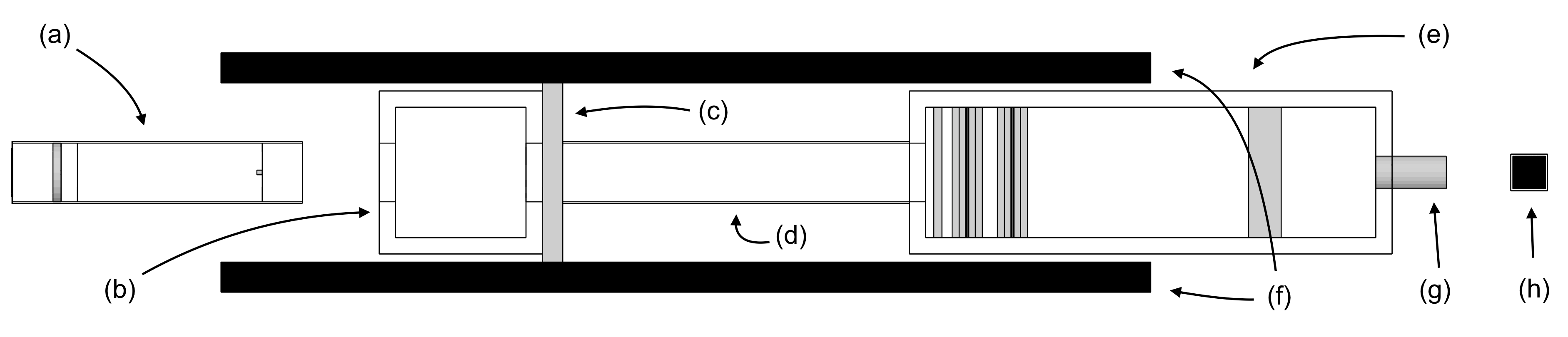
| 12:24, 6 July 2017 | Beamline top down.png (file) | 119 KB | A top-down view of the beamline showing all its components: (a) first aluminium tube, (b) first aluminium box, (c) iron block, (d) second aluminium tube, (e) second aluminium box (dosimetry box), (f) shielding made of borated plastic, (g) brass nozzle, (h) water volume. | 1 | |
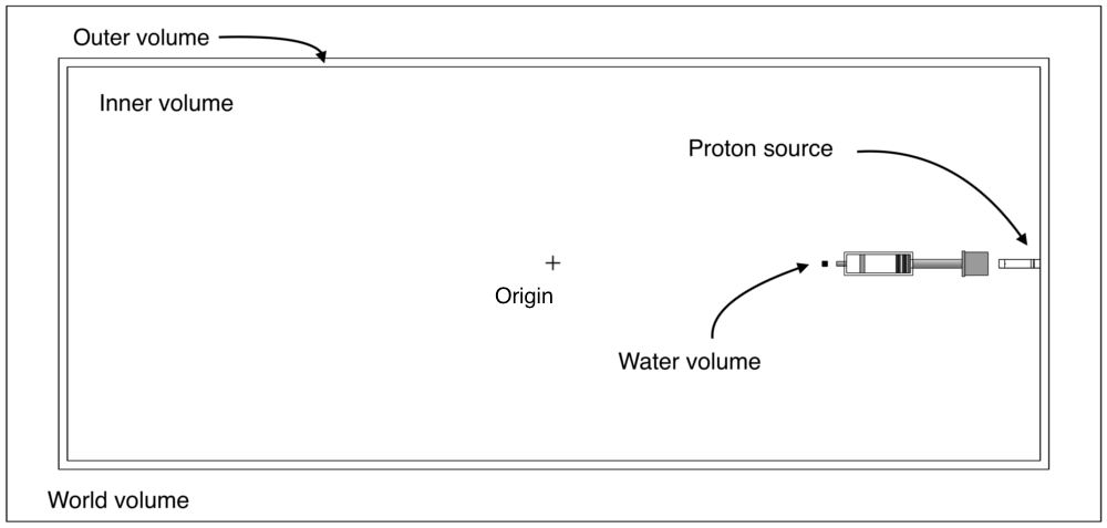
| 12:03, 6 July 2017 | TreatmentRoomSchematic.png (file) |  |
37 KB | Included origin. | 5 |