Proton Calorimetry/Experimental Runs/2025/Trento 2025-03: Difference between revisions
| Line 71: | Line 71: | ||
# FLASH measurements at 245 MeV. | # FLASH measurements at 245 MeV. | ||
=== Calibration === | === Calibration FLASH === | ||
DDC232 FSR should be determined at max beam current starting from minimum FSR value that does not give signal saturation. This could require 2 or 3 beam deliveries. | |||
{| class="wikitable" | {| class="wikitable" | ||
!Run number | !Run number | ||
Revision as of 10:35, 4 February 2025
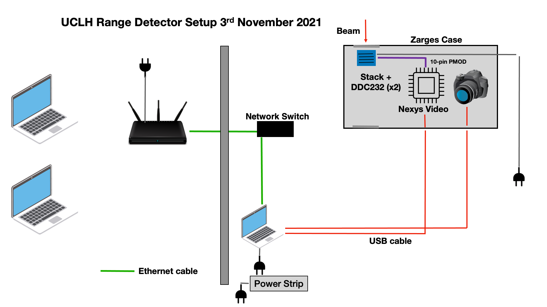
Experiment Equipment
| Item | Notes |
|---|---|
| Network Hub | Set in control room to take output from experimental room ethernet connection. Control laptops connected via 5GHz WiFi. |
| Control Laptop x2 | 1 for remote control of FPGA, 1 for notes/web GUI. |
| Ethernet Cable x 2 | To connect DAQ laptop to network in the experimental room, control laptop to network in control room. |
| Portable Enclosure | |
| Scintillator stacks | 4 Modules (to cover the full clinical range, from 60 to 250 MeV) |
| Scintillating fibers module | 1 2D Module |
| DAQ laptop x1 | Control photodiode acquisition. |
| Nexys Video FPGA development board. | For interfacing between DDC232 and PC. |
Schematic
Experiment Plan
- Set up mains cabling and networking in treatment and control rooms.
- no beam
- Install Peli case on treatment couch.
- no beam
- Background
- no beam
- Calibration shoot-through measurements of 4 stack modules: either rotating case or modules for back shoot-through.
- 8 beam deliveries (2 beam deliveries (back and forth) per each module):
| Run number | Detector config | Beam Energy (MeV) | Beam Current (nA) | Physical thickness (mm) | D80 measured (mm) | WET (mm) | RSP | Comments |
|---|---|---|---|---|---|---|---|---|
| 33 | Stack 1 front | 245 | 18.8 (18.7) | 95.95 | 198.69 | 98.24 | 1.024 | |
| 34 | Stack 1 back | 245 | 18.8 (18.7) | 95.95 | 198.74 | 98.19 | 1.023 | |
| 36 | Stack 2 front | 245 | 18.8 (18.7) | 96.81 | 198.51 | 98.42 | 1.016 | |
| 37 | Stack 3 front | 245 | 18.8 (18.7) | 95.48 | 199.78 | 97.15 | 1.017 | |
| 40 | Stack 4 front | 245 | 18.8 (18.7) | 94.07 | 202.26 | 94.67 | 1.006 | |
| 41 | Empty Box | 245 | 18.8 (18.7) | 0.012 | 296.93 | 0 | 0 | |
| 42 | No Box | 245 | 18.8 (18.7) | 0 | 296.90 | 0 | 0 |
- Pristine Bragg peak measurements at clinical current for full clinical range.
- FLASH measurements at 245 MeV.
Calibration FLASH
DDC232 FSR should be determined at max beam current starting from minimum FSR value that does not give signal saturation. This could require 2 or 3 beam deliveries.
| Run number | Detector | Beam Energy (MeV) | Estimated Range (mm) | Current (nA) | Spot size (mm, FWHM) | DDC232 FSR (pC) | DDC232 Integration Time (us) | Degrader WET (mm) | Comments | Photodiode QB Fit | Replay Fit |
|---|---|---|---|---|---|---|---|---|---|---|---|
| n | Stack 1 | 245 MeV | max | min FSR that does not saturate the signal | 170 | Shoot through front | N/A | ||||
| n | Stack 1 | 245 MeV | max | min FSR that does not saturate the signal | 170 | Shoot through back | N/A | ||||
| n | Stack 1 | Background | - | N/A | - | 170 | N/A | ||||
| n | Stack 2 | 245 MeV | max | min FSR that does not saturate the signal | 170 | Shoot through front | N/A | ||||
| n | Stack 2 | 245 MeV | max | min FSR that does not saturate the signal | 170 | Shoot through back | N/A | ||||
| n | Stack 2 | Background | - | N/A | - | 170 | N/A | ||||
| n | Stack 3 | 245 MeV | max | min FSR that does not saturate the signal | 170 | Shoot through front | N/A | ||||
| n | Stack 3 | 245 MeV | max | min FSR that does not saturate the signal | 170 | Shoot through back | N/A | ||||
| n | Stack 3 | Background | - | N/A | - | 170 | N/A | ||||
| n | Stack 4 | 245 MeV | max | min FSR that does not saturate the signal | 170 | Shoot through front | N/A | ||||
| n | Stack 4 | 245 MeV | max | min FSR that does not saturate the signal | 170 | Shoot through back | N/A | ||||
| n | Stack 4 | Background | - | N/A | - | 170 | N/A |