Proton Calorimetry/Experimental Runs/2021/Apr1: Difference between revisions
SaadShaikh (talk | contribs) No edit summary |
SaadShaikh (talk | contribs) No edit summary |
||
| Line 9: | Line 9: | ||
*In all runs, an integration time of 170us and full-scale range of 350pC is used. | *In all runs, an integration time of 170us and full-scale range of 350pC is used. | ||
'''Traces saved in [http://www.hep.ucl.ac.uk/pbt/wikiData/ | '''Traces saved in [http://www.hep.ucl.ac.uk/pbt/wikiData/images/DDC232/20210401 /unix/www/html/pbt/wikiData/images/DDC232/20210401]''' | ||
{|class="wikitable" | {|class="wikitable" | ||
Revision as of 10:44, 7 April 2021
Daisy chain tests of second DDC232 prototype in D109
Aim: Debug "mirroring" issues when daisy-chaining more than 2 DDC232s boards. Test signal quality across boards using 500MHz oscilloscope.
Notes
- 3 DDC232 boards have S12915-16R photodiodes.
- 4th DDC232 board has 1k ohm resistors.
- In the runs below, boards are enumerated right to left, with the right-most board (1st board) connected to the FPGA.
- In all runs, an integration time of 170us and full-scale range of 350pC is used.
Traces saved in /unix/www/html/pbt/wikiData/images/DDC232/20210401
| Run | Board Configuration | Description | Video |
|---|---|---|---|
| 1 | 3, 1 | Rotation of boards followed by swept covering of a few photodiodes in turn with black cloth. Boards initially facing downwards but rotated upwards to expose to room lighting. Sweep begins around 20s mark. Note that there is no mirroring and both boards behave as expected. | 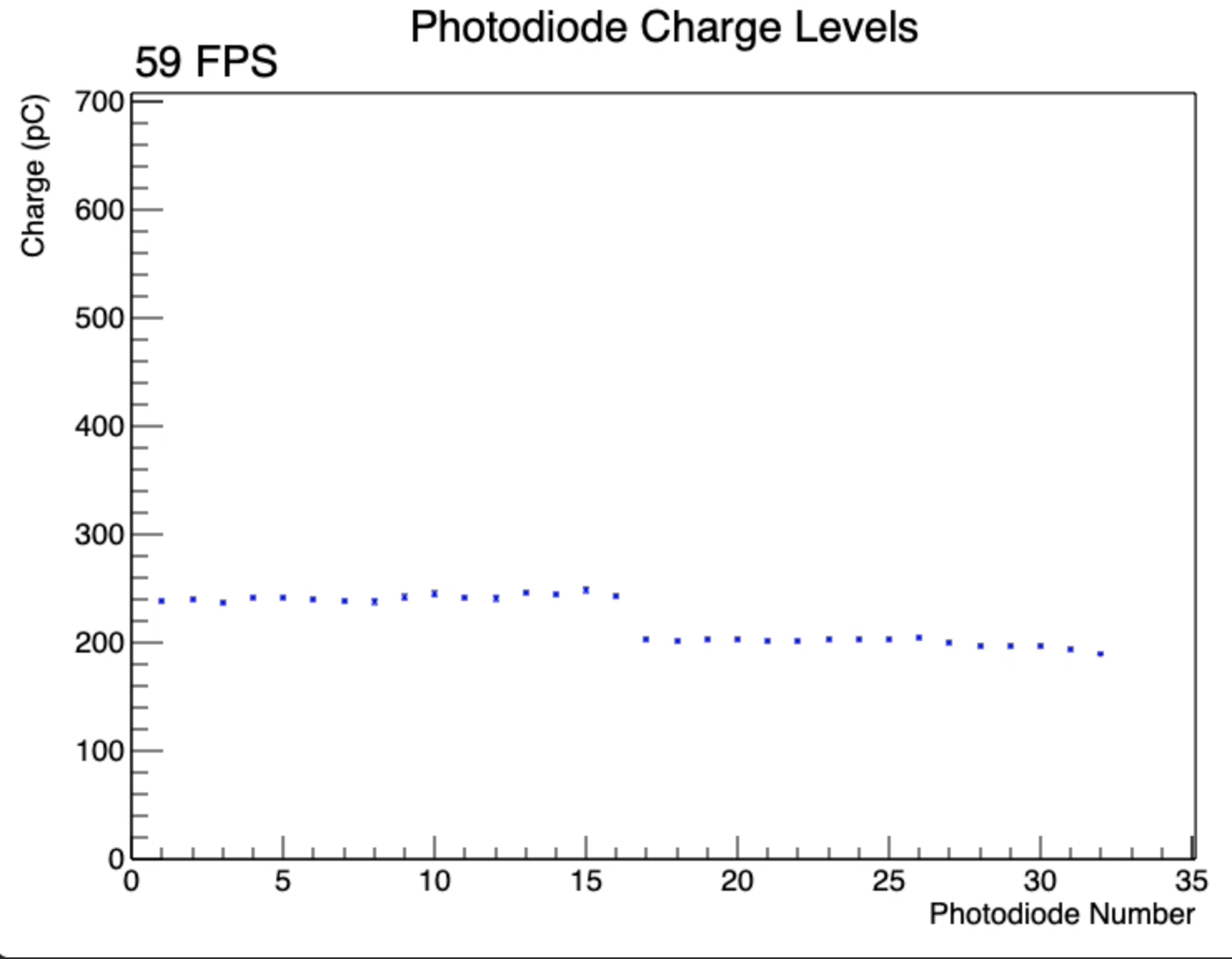 |
| 2 | 3, 4 | Rotation of boards followed by swept covering of a few photodiodes in turn with black cloth. Boards initially facing downwards but rotated upwards to expose to room lighting. Sweep begins around 10s mark. Note similar behaviour to above. | 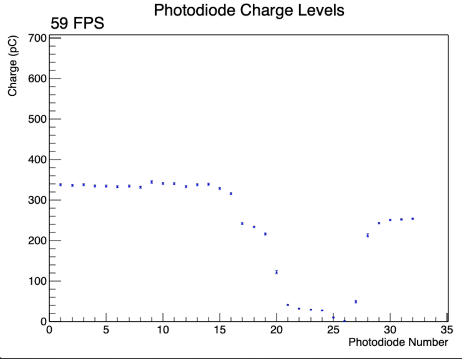 |
| 3 | 3, 2 | Rotation of boards followed by swept covering of a few photodiodes in turn with black cloth. Boards initially facing downwards but rotated upwards to expose to room lighting. Sweep begins around 5s mark. Note that channels 1-16 show no output as they have been replaced with resistors; also, there is no mirroring. | 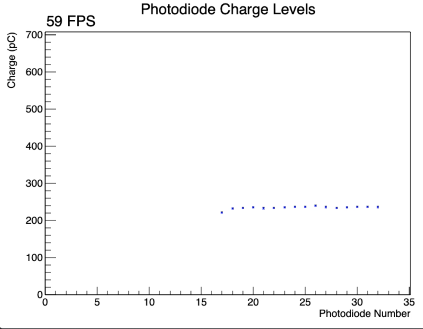 |
| 4 | 3, 1, 4 | Rotation of boards followed by swept covering of a few photodiodes in turn with black cloth. Boards initially facing downwards but rotated upwards to expose to room lighting: boards rotated repeatedly to examine signal dropouts on board 4. Sweep begins around 47s mark. Note that the mirroring is the lowest of the photodiode pairs on boards 1 and 4. Note also that very noisy signals and signal dropouts are seen on board 4 (photodiodes 1-16) and that this is not replicated on board 1; so whatever is causing this noisy behaviour does not contribute to the mirroring. Compare this to run 2 above where these noisy signals and dropouts are not seen. | 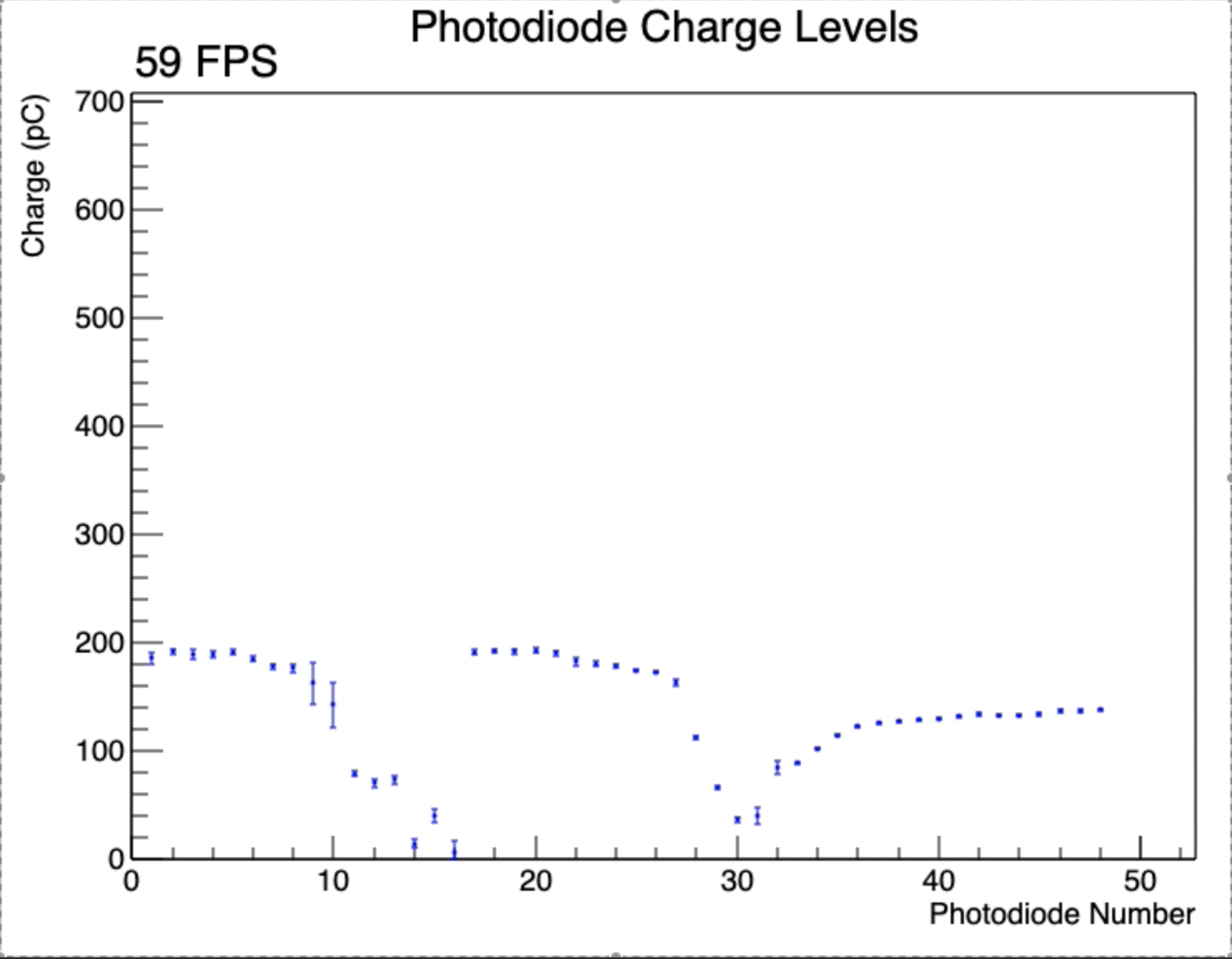 |
| 5 | 3, 4, 1 | Rotation of boards followed by swept covering of a few photodiodes in turn with black cloth. Reording of boards from run 4 above. Boards initially facing downwards but rotated upwards to expose to room lighting. Sweep begins around 25s mark. Note that the behaviour is similar to run 4 with board 4 still noisy and that this noise is not mirrored but that the low signals are mirrored between boards 1 and 4. | 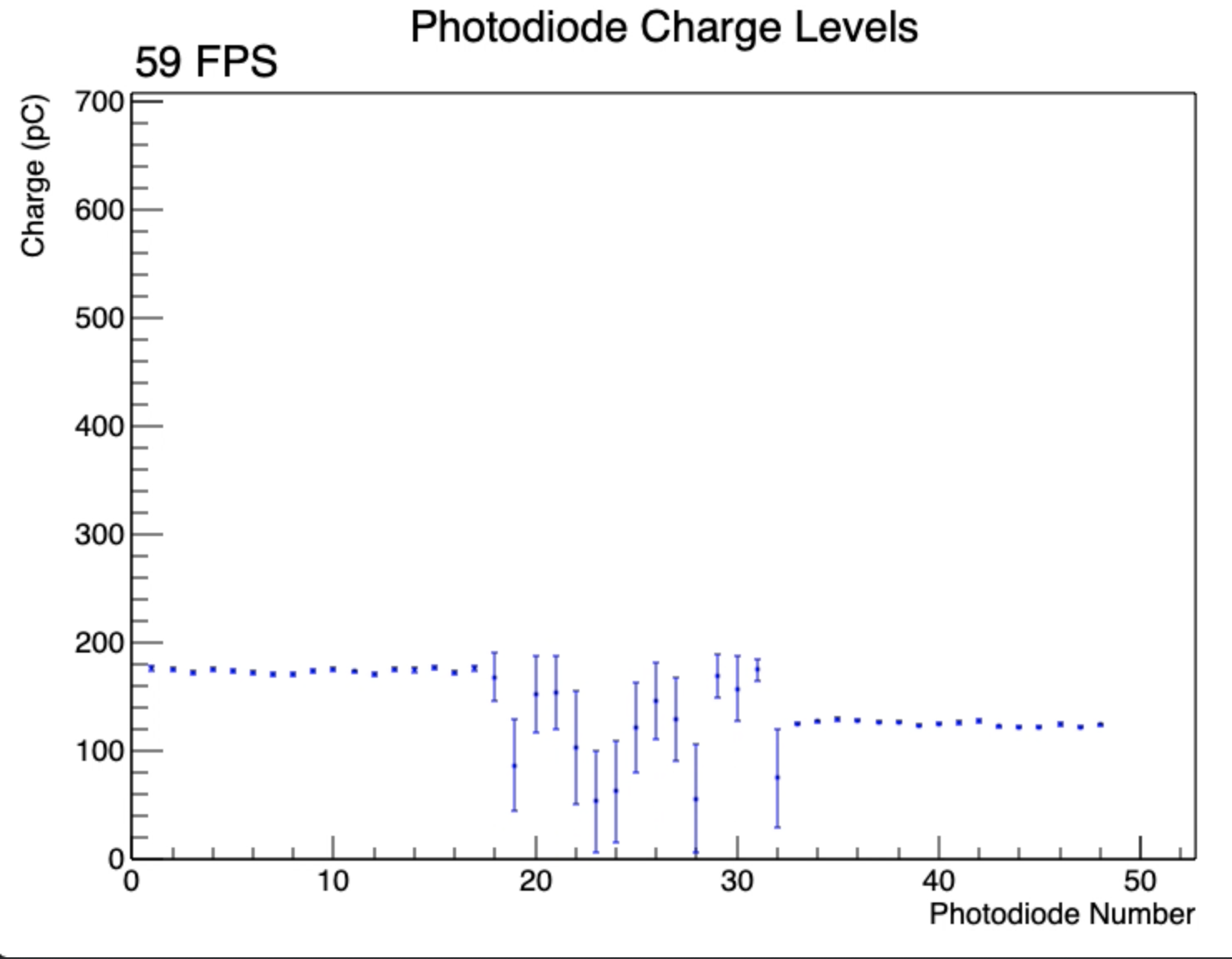 |
| 6 | 3, 4, 1 | Swept uncovering of each photodiode in turn. Sweep begins near the start of the video but it only seen in the signals once board 1 is fully uncovered and board 4 starts to be uncovered. Mirroring appears to be connected to lowest output, not largest, for mirrored pairs. | 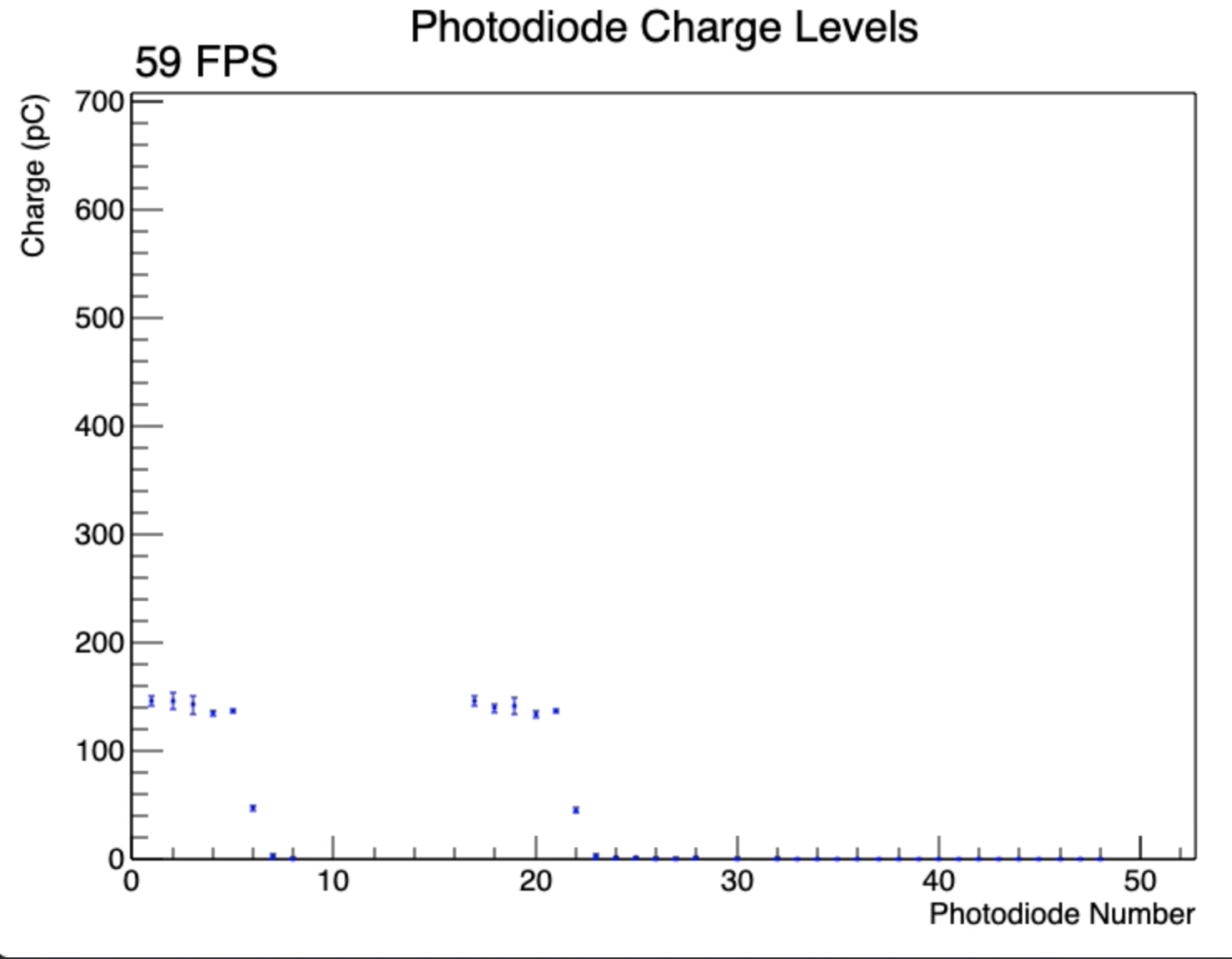 |
| 7 | 3, 4, 1 | Swept uncovering of each photodiode in turn - in opposite direction to run 6 - followed by board rotation and swept covering with finger. Note that board 4 shows zero output during uncovering due to signal dropouts associated with rotation. Low signals around 1m25s mark are a results of covering photodiodes partially with a finger. | 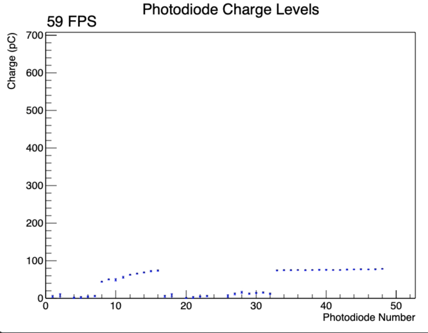 |
| 8 | 4, 3, 1 | Swept uncovering of each photodiode in turn followed by board rotation and swept covering with finger. Repeat of run 7 above but with board reordering. Note that board 4 no longer shows noise when rotated now that its the last board in the chain. | 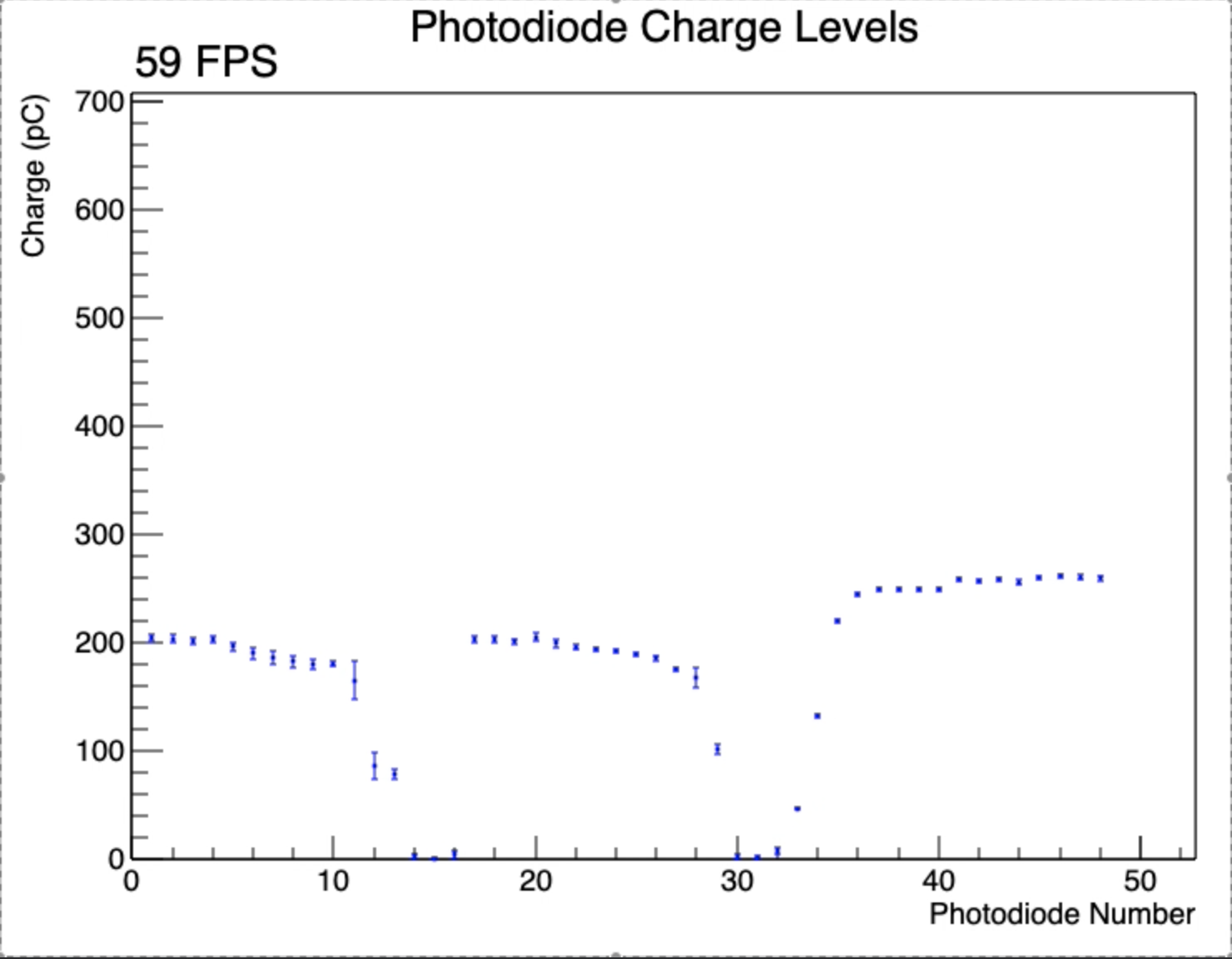 |
| 9 | 3, 4, 2 | Rotation of boards followed by swept covering of a few photodiodes in turn with black cloth. Now includes board 2 with resistor-shorted photodiode connections. Note that neither boards 4 or 2 show any output, corroborating that low values are mirrored despite board 4 being exposed to light. | 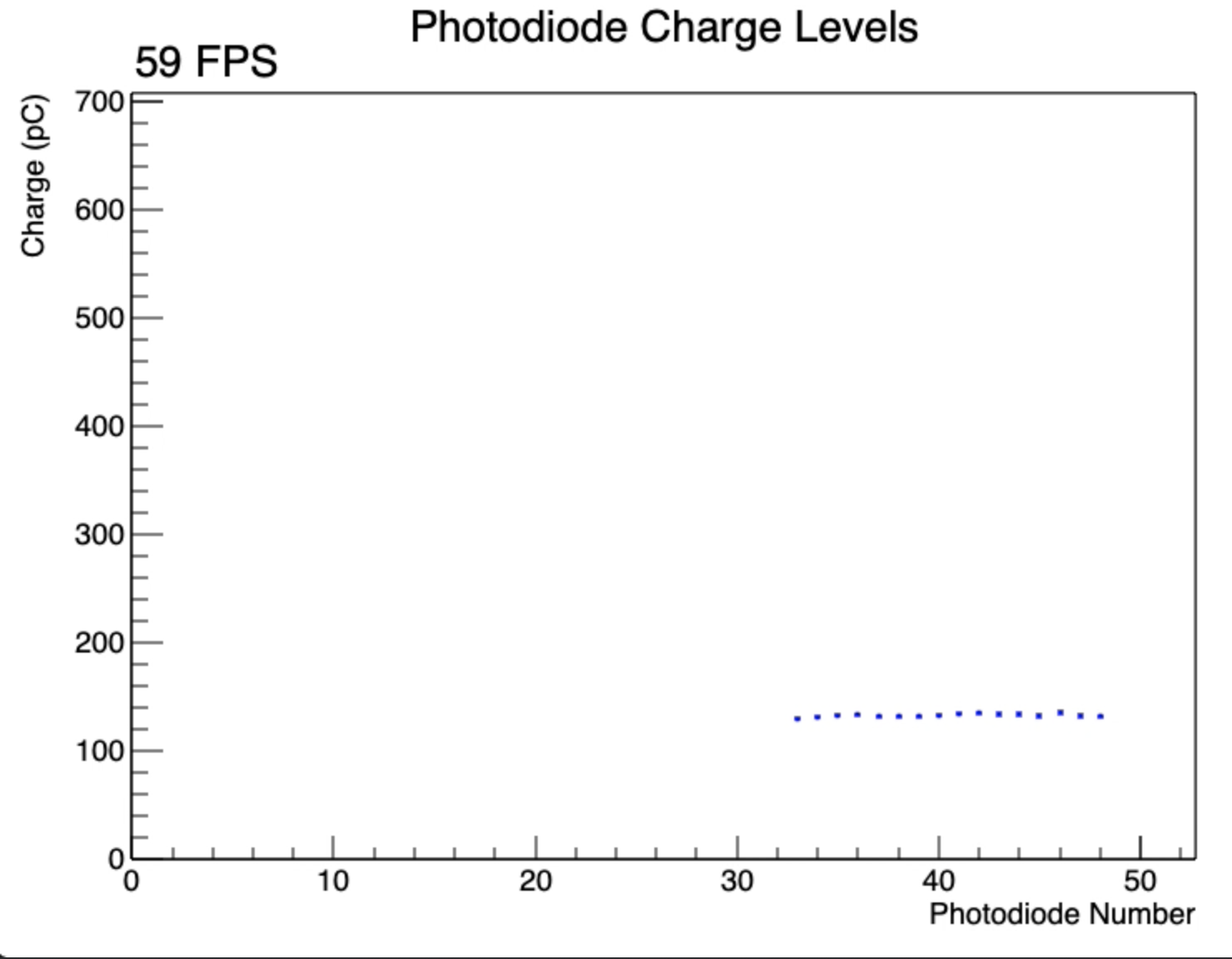 |
| 10 | 3, 2, 4 | Rotation of boards followed by swept covering of a few photodiodes in turn with black cloth. Reording of boards from run 9 above: note that the behaviour is similar with no output from boards 2 and 4. | 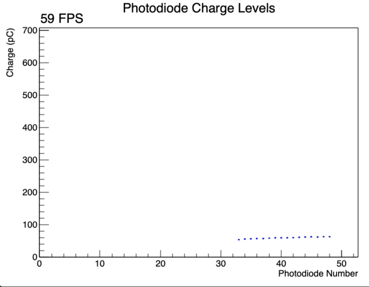 |
| 11 | 3, 1, 4, 2 | board rotation and sweep covering of photodiodes | 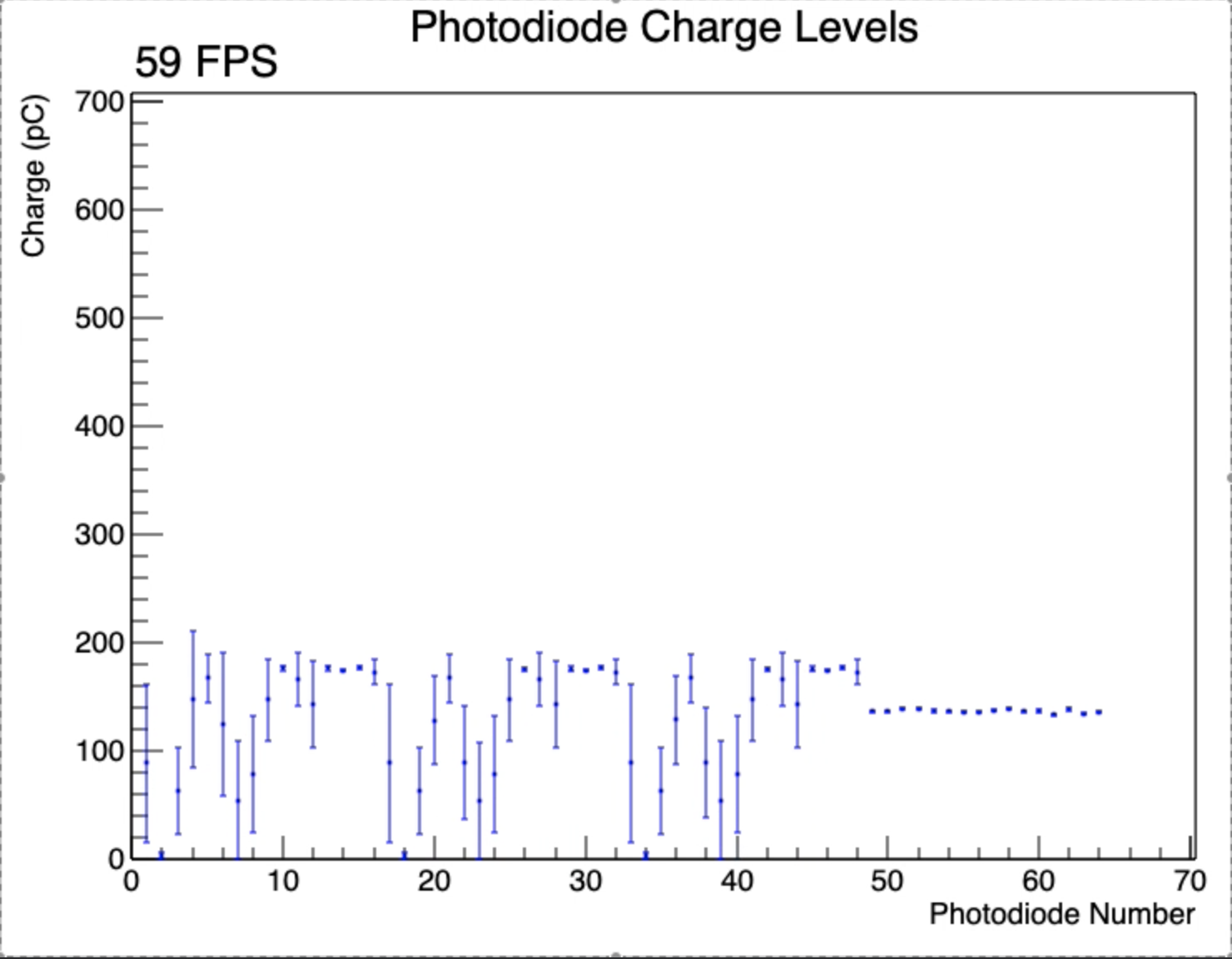 |
| 12 | 3, 4, 2, 1 | board rotation and sweep covering of photodiodes | 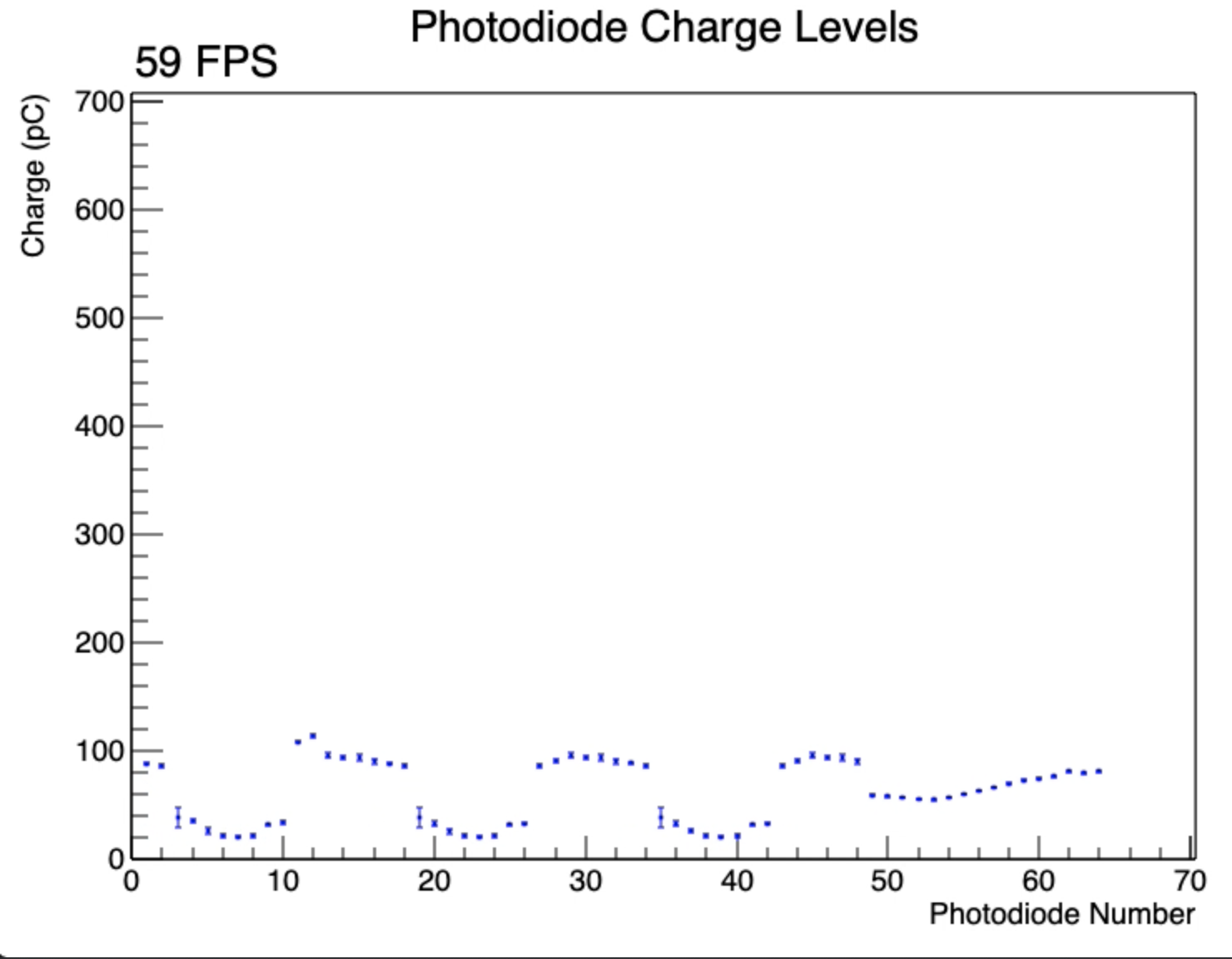 |
| 13 | 3, 2, 1, 4 | board rotation and sweep covering of photodiodes |  |