LI Pulser Box and Fibre Bundle
Tests
Intro:
Need to test pulser boxes and
light injection fibres bundles upon arrival at Soudan
Pulser boxes are installed, one
in each electronics crate on the middle level, in the space above the Wener
power supply and below the RPS unit
Light injection fibre bundles are
installed to the planes before each plane is lifted, (see installation
Word document written by Richard White, Sussex
for more details)
Testing of pulser
boxes involves:
-
checking that electronics boards inside
pulser boxes have not been dislodged in transit
-
checking that all LEDs are working
-
checking for broken fibres
-
measuring light emitted from each fibre
in each connector at the pulser box via 1m test fibre bundle
Testing of
fibre bundles involves:
-
checking for damaged fibre bundles and
broken fibres before installation
-
measuring % transmission of fibres compared
to a 1 metre test fibre (from pulser box tests)
All measurements are made using
Sussex testing apparatus.
Measurements are currently written
into a root tree; for instructions, follow this link.
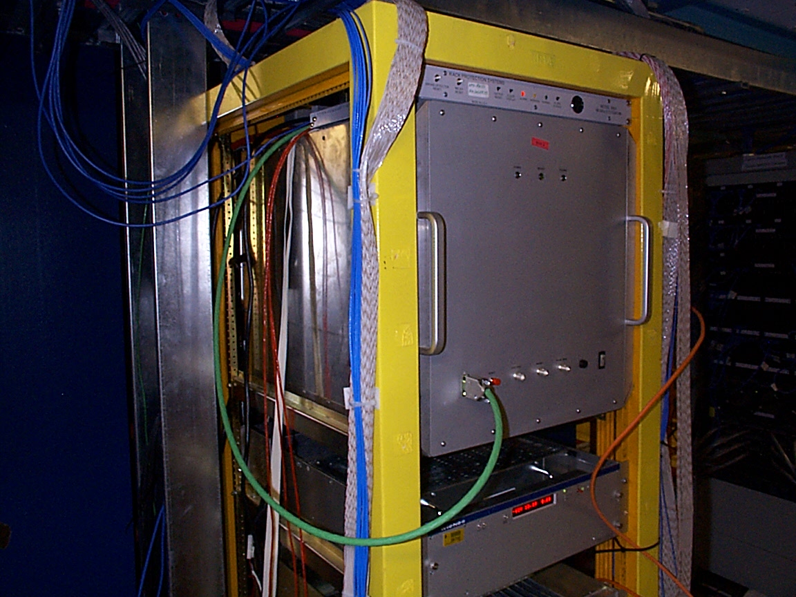
This is a pulser box. The three lights
at the top on the front are, from left to right: power (red), ready (yellow)
and pulsing (blue). Beneath, from left to right, there is: the RS232 connector
which is connected via the green cable to the EDAS connection on the RPS
unit; the red reset button; the external trigger BNC connector; something
I can't remember; the pulse monitor; fuse; and on/off power switch.
Outline:
Sussex Test Apparatus
-
Consists of a set of 20 PIN diodes,
calibrated to have identical responses, connected to a single amplifier.
-
A fibre bundle is connected at one end
to the pulser box via a 20-way connector and at the other to the box containing
the PIN diodes. The fibres have metal connectors at the end and can be
plugged directly into recesses in the PIN diode box, one fibre per PIN.
-
Only a single fibre is pulsed at a time
by the pulser box, (a result of the fact that only a single LED can be
pulsed at a time in the pulser box), and so only light from one fibre at
a time is amplified.
-
The signal from the amplifier is sent
to a picoscope which has a PC interface. The picoscope is triggered by
a signal from a BNC connection on the front of the pulser box. This sends
out a constant 4V signal when the box is on. When the pulser pulses the
signal dips to below 0V for a short time.
-
The PC controls both the flashing of
the pulser box and the analysis of the pulses as sampled by the picoscope.
A set of three LabView programs can be used for controlling the pulser
box and for sampling the pulse heights of the signals measured by the PINs,
(see separate document for use of the LabView
programs).
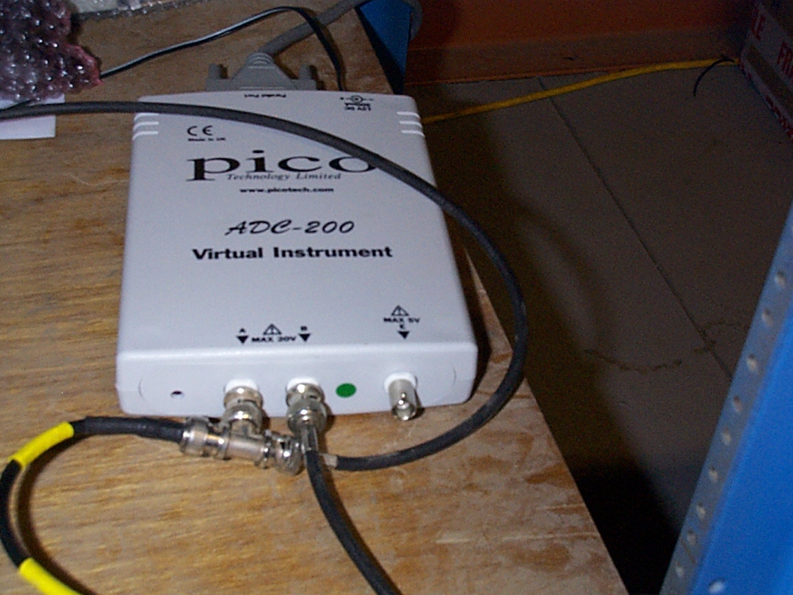
This is the picoscope. Channel
A is connected with the T-junction. The signal from the PIN array amplifier
is split to go to the pico and to an oscilloscope. Channel B is connected
to the pulse monitor on the front of the pulser box. At the rear of the
box a parrallel port connector is seen. This is connected to the parrallel
port of the LI laptop.
Testing a Pulser Box
A pulser box contains 20 LEDs and
is controlled via an RS232 cable from the serial port of a Laptop or over
ethernet via an EDAS box. The boxes have 64 regular connectors, each with
20 fibres, one from each of the LEDs in the box. There is also one spare
connector and two connectors for PIN fibres that go to PIN diodes on the
front end electronics boards mounted on each MUX box. The fibres in the
PIN connectors are made to be significantly brighter than the other fibres,
as PIN diodes are not as sensitive as PMTs to low light levels.
LABELLING THE CONNECTORS ON THE
BACK OF THE PULSER BOX: connectors are labelled in order of plane number
they serve (i.e. the connector serving east side of plane 65 will be connector
1 on pulser box 2, west side of plane 100 will be connector 36 on pulser
box 3); Connector 65 on a box is the SPARE, 66 is the LOW gain PIN and
67 is the HIGH gain PIN connector. (Also see LI mapping page.)
-
Using an Allen key the front of the
pulser box can be opened. Open carefully as there are wires from electronics
boards within the box soldered to the front panel. Check that the electronics
boards have remained firmly in place after shipping. If not, reseat the
boards.
-
Remove the blacking connectors at the
back of the pulser box and use the LabView sequential flasher vi program,
to check that there are no broken fibres in the box and that all the LEDs
are working. If there are broken fibres, contact Phil Harris for advice.
-
If the same fibre position in all connectors
always looks dark, this implies an LED problem. Burnt out LEDs can be replaced
inside the pulser box. Again if this has to be done, contact Phil Harris
for advice.
-
To test the light output from each fibre
from each connector, connect the 1 metre test cable to one of the positions
on the back of the pulser box (see section below "Attaching Fibre Bundles
to Pulser Boxes") and connect the single fibre ends to the appropriate
position in the 20-PIN diode array, (always connecting fibre 1 to PIN 1,
etc. removes any possible error due to variations in the PIN diode responses.
This is important later when measuring the transmission of the fibre bundles
compared to the test fibres).
-
Run the appropriate LabView program
using the settings stated in the LabView document and save the text file
produced. The file lists the average value for the peak of the pulse in
millivolts as measured by the picoscope, for each LED, i.e. for each fibre
in that connector.
-
Once all connectors have been measured,
use root macro to write all the information into a tree, (see instructions
on how to do this here).
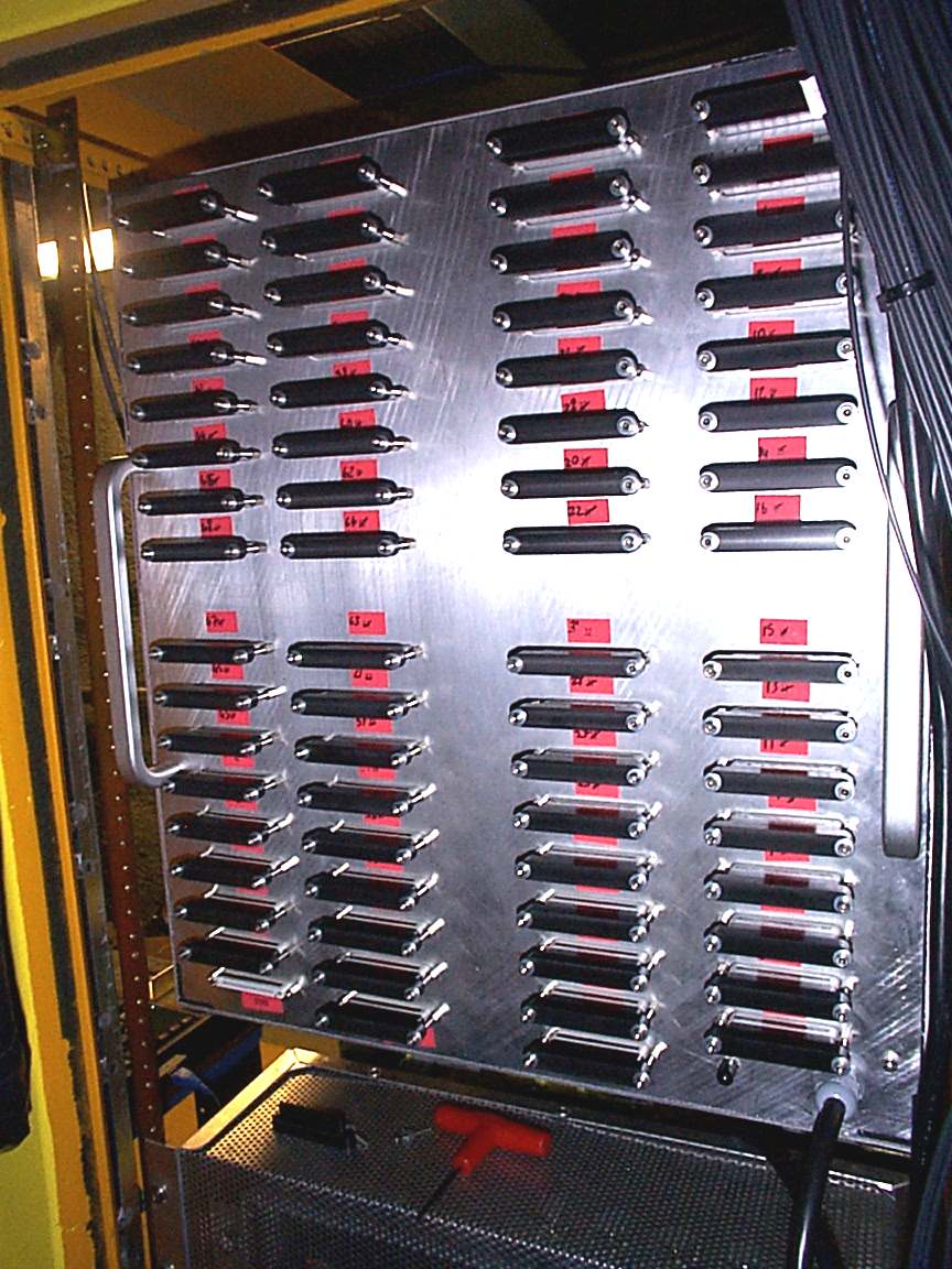
This is the back of the pulser
box. Each of these connectors need to be tested for light output using
the test setup. Each connector has 20 fibres, one fibre from each LED in
the box. The 64 connectors which supply light to the scintillator modules
are the 4 groups of 16 that can be seen. The bottom three connectors are,
from left to right: spare, low PIN and high PIN connectors. To the right
of the high PIN connector is the connection for the single trigger
fibre; and to the right of that is the power lead which is just plugged
into the wall supply.
Testing Fibre Bundles
-
Each fibre bundle consists of 20 clear
fibres of varying lengths with a 20-way connector at one end and individual
metal connectors at the other. The 20-way is plugged into the back of the
pulser box to the spare connector (see section below "Attaching Fibre Bundles
to Pulser Boxes") and the 20 fibre ends into the PIN diode box ,(fibre
1 to PIN 1, etc).
-
Dab the tips of the fibre ends with
isopropyl alcohol before inserting them into the PIN diode box. Only use
special lens cleaning papers for cleaning.
-
Unlike in the case of the test cable,
the connectors on the individual fibre ends are not designed to fit perfectly
into the PIN diode box, so ensure that the fibres are pushed in as far
a they can go.
-
Once again the LabView program can then
be run using appropriate settings and a text file saved for each fibre
bundle.
-
The data for each bundle can be added
to an existing tree containing all the values for the % transmission for
all the LI fibres, (see instructions on how to do this here).
-
ENSURE THAT PULSER BOX DOES NOT CONTINUE
TO PULSE AFTER TESTING. THIS CAN CAUSE PREMATURE LED DEATH! If blue LED
on front of pulser box is on when you expect pulser box to be off, hit
the red reset button on the front panel.
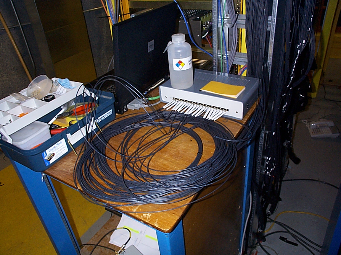
This is the test setup. The grey
box is the array of 20 PIN diodes. A fibre bundle is currently plugged
into the box. The other end of the fibre bundle is plugged into the back
of the pulser box itself. Notice that care was taken when plugging in the
fibre bundle to stay clear of the minimum bend radius of the fibre which
is approximately 1 inch. Also notice in this photo, the serial and parrallel
port connections in the back of the laptop coming from the pulser box and
the picoscope respectively.
Attaching Fibre Bundles to
Pulser Boxes
-
Use isopropyl alcohol to clean the 20-way
connector and it's mate before connecting the bundle at the pulser box
end. Only use special lens cleaning papers for cleaning.
-
Make sure that step dowels are used
when testing fibre bundles; this causes the connectors to be installed
upside-down. (IMPORTANT: Check whether or not the connector needs
step-dowels. In some cases e.g. the 1m test cable and the first 4 sets
of PIN fibres, the connectors were made correctly and step-dowels are not
necessary. If step dowels are needed, an offset between the fibres in a
pulser box connector and the fibres in the fibre bundle connector can clearly
be seen.)
-
If grease is to be used, use a syringe
to put a small amout of grease along the length of the connector, over
the fibres. Then use a latex glove and in one motion smear the grease along
the connector. Push the connectors together and tighten screws without
allowing the connectors to come apart. (If the connectors do come apart,
air bubbles may be introduced which will ruin the optical connection.)
-
Use washers on the screws when attaching
the fibre bundles to the pulser box. Be sure not to overtighten the screws.
-
Use a strip of black insulating tape
to light tight the pulser box-fibre bundle connection.
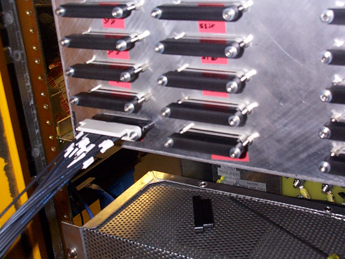
This is an example of a 20-way
connector from a fibre bundle connected to the back of a pulser box. Notice
that the connector is upside-down
due to the insertion of the step dowels. Also the strip of black tape ensures
that the connection is light tight.
Back to main
LI installation page