Proton Calorimetry/Experimental Runs/2022/Jun16: Difference between revisions
SaadShaikh (talk | contribs) No edit summary |
SaadShaikh (talk | contribs) |
||
| Line 52: | Line 52: | ||
== Experiment Plan == | == Experiment Plan == | ||
*Background & calibration shoot-throughs (background at all 8 DDC232 full-scale ranges) | '''Rev. B Prototype''' | ||
*Pencil beams, 70- | *Background & calibration shoot-throughs (background at all 8 DDC232 full-scale ranges – likely 12.5 pC is most appropriate FSR) | ||
*Pencil beams, 70-130 MeV, 10 MeV steps, in both directions into stack. For direction with Bragg peak in clear sheets, test 2 currents (high/low) | |||
* | |||
* | '''Rev. C Prototype''' | ||
*Background & calibration shoot-throughs (12.5 pC FSR) | |||
*Pencil beams, 70-110 MeV, 5 MeV steps, at clinical current. | |||
== Experiment Notes == | == Experiment Notes == | ||
Revision as of 16:58, 18 June 2022
Afternoon test at UCLH with photodiodes and CMOS sensor.
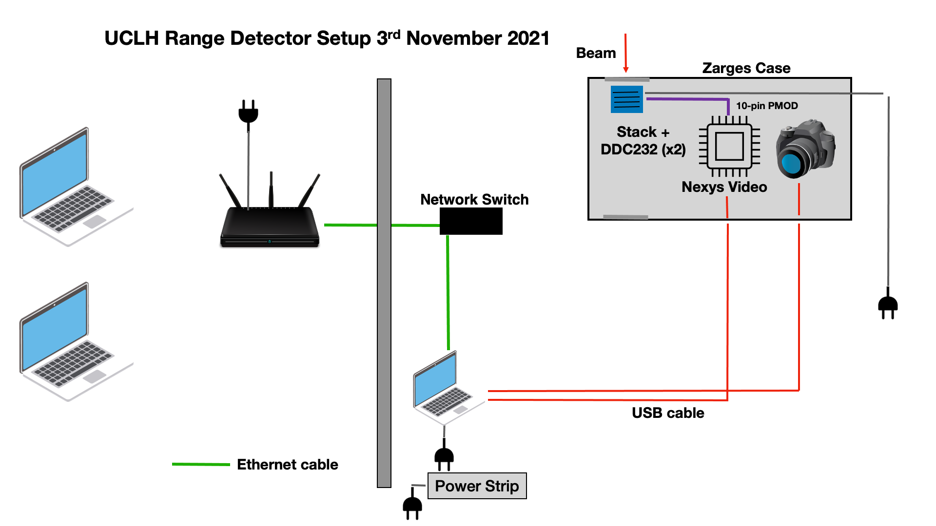
Experiment Equipment
| Item | Notes |
|---|---|
| Network Hub | Set in control room to take output from experimental room ethernet connection. Control laptops connected via 5GHz WiFi. |
| Control Laptop x3 | 2 for remote control of CMOS sensor and FPGA, 1 for notes/web GUI. |
| Ethernet Cable x 3 | To connect DAQ laptops to network in the experimental room, network hub to network in control room. |
| Portable Enclosure | Modified Big Zarges Waterproof Wheeled Equipment Case.
Features mount for scintillator stack, front and back openings for beam, patch panel with ports for SHV, BNC, SMA, USB, Camera Link cables. |
| Rev. B Scintillator stack | 49 (25 clear, 23 white painted and 1 black painted) X x 100 mm, Y x 100 mm and Z x (approx) 2.8 mm sheets in ascending order from the front/beam of the end of the scintillator. Sheet numbers from front to end (in beam direction): 79, 68, 73, 62, 81, 72, 64, 67, 65, 71, 78, 77, 74, 75, 85, 82, 83, 76, 70, 80, 69, 84, 63, 66, 61, 34, 43, 32, 8, 40, 37, 38, 47, 46, 33, 42, 9, 39, 44, 49, 50, 31, 1, 45, 3, 54, 5, 51, 26. Full stack thickness measurements (in mm): 138.12, 137.74, 137.74. |
| Rev. C Scintillator stack | 32 X x 105 mm, Y x 105 mm and Z x (approx) 3 mm sheets (21 3.4 mm and 11 2.0 mm) in ascending order from the front/beam of the end of the scintillator. Sheet numbers from front to end (in beam direction): 117, 113, 134, 110, 108, 128, 107, 106, 127, 105, 104, 125, 103, 102, 124, 101, 98, 123, 97, 96, 122, 94, 93, 121, 92, 90, 120, 89, 88, 119, 87, 135. Full stack thickness measurements (in mm): 95.87, 95.96, 95.97. |
| DAQ laptop x2 | Control CMOS sensor and photodiode acquisition. |
| ISDI CMOS sensor | sensor pixel dimension: 1030 x 1536. NO optical grease between scintillator and sensor. Connected to DAQ PC via Camera Link cable. |
| Nexys Video FPGA development board. | For interfacing between DDC232 and PC. |
| Rev. B Texas Instruments DDC232 custom circuit board (x3) | Each housing 16x Hamamatsu S12915-16R photodiodes, coupled directly to scintillator sheets. Aligned by eye to scintillator sheets. |
| Rev. C Texas Instruments DDC232 custom circuit board (x1) | Housing 32x Hamamatsu S12915-16R photodiodes, coupled directly to scintillator sheets. Aligned by eye to scintillator sheets. |
| Gloves | For handling scintillator |
Schematic
Experiment Plan
Rev. B Prototype
- Background & calibration shoot-throughs (background at all 8 DDC232 full-scale ranges – likely 12.5 pC is most appropriate FSR)
- Pencil beams, 70-130 MeV, 10 MeV steps, in both directions into stack. For direction with Bragg peak in clear sheets, test 2 currents (high/low)
Rev. C Prototype
- Background & calibration shoot-throughs (12.5 pC FSR)
- Pencil beams, 70-110 MeV, 5 MeV steps, at clinical current.
Experiment Notes
Range calorimeter measurements with CMOS sensor + photodiodes.
Images from Sensor: /unix/www/html/pbt/wikiData/images/UCLH_Jun2022/CMOS
Photodiode hexadecimal data: /unix/pbt/data/uclh/20220616/DDC232
| Run number | Beam Energy (MeV) | Estimated Range (mm) | Current (nA) | Spot size (mm, FWHM) | DDC232 FSR (pC) | DDC232 Integration Time (us) | Degrader WET (mm) | Comments | Photodiode QB Fit | CMOS QB Fit | PDL Comparison | Replay Fit |
|---|---|---|---|---|---|---|---|---|---|---|---|---|
| 0 | Background | N/A | N/A | N/A | 350 | 170 | 0 | room light off | N/A | N/A | N/A | N/A |
| 1 | Background | N/A | N/A | N/A | 300 | 170 | 0 | room light off | N/A | N/A | N/A | N/A |
| 2 | Background | N/A | N/A | N/A | 250 | 170 | 0 | room light off | N/A | N/A | N/A | N/A |
| 3 | Background | N/A | N/A | N/A | 200 | 170 | 0 | room light off | N/A | N/A | N/A | N/A |
| 4 | Background | N/A | N/A | N/A | 150 | 170 | 0 | room light off | N/A | N/A | N/A | N/A |
| 5 | Background | N/A | N/A | N/A | 100 | 170 | 0 | room light off | N/A | N/A | N/A | N/A |
| 6 | Background | N/A | N/A | N/A | 50 | 170 | 0 | room light off | N/A | N/A | N/A | N/A |
| 7 | Background | N/A | N/A | N/A | 12.5 | 170 | 0 | room light off (continued) | N/A | N/A | N/A | N/A |
| 8 | 240 | N/A | 10 | N/A | 350 | 170 | 50 | LH shoot through; 270° gantry; CMOS sensor saturated | N/A | N/A | N/A | N/A |
| 9 | 240 | N/A | 10 | N/A | 12.5 | 170 | 50 | LH shoot through; 270° gantry; CMOS sensor saturated | N/A | N/A | N/A | N/A |
| 10 | 240 | N/A | 10 | N/A | 12.5 | 170 | 50 | RH shoot through; 90° gantry; CMOS sensor saturated | N/A | N/A | N/A | N/A |
| 11 | 200 | N/A | 90 | N/A | 12.5 | 170 | 50 | RH shoot through; 90° gantry; CMOS sensor saturated; | N/A | N/A | N/A | N/A |
| 12 | 200 | N/A | 20 | N/A | 12.5 | 170 | 50 | RH shoot through; 90° gantry; CMOS sensor fine; | N/A | N/A | N/A | N/A |
| 13 | 130 | N/A | 50 | N/A | 12.5 | 170 | 0 | 90° gantry; CMOS sensor slight saturation; | N/A | N/A | N/A | N/A |
| 14 | 120 | N/A | 60 | N/A | 12.5 | 170 | 0 | 90° gantry; CMOS sensor saturated; | N/A | N/A | N/A | N/A |
| 15 | 120 | N/A | 270 | N/A | 12.5 | 170 | 0 | 90° gantry; CMOS sensor saturated; | N/A | N/A | N/A | N/A |
| 16 | 110 | N/A | 70 | N/A | 12.5 | 170 | 0 | 90° gantry; CMOS sensor saturated; | N/A | N/A | N/A | N/A |
| 17 | 110 | N/A | 300 | N/A | 12.5 | 170 | 0 | 90° gantry; CMOS sensor saturated; | N/A | N/A | N/A | N/A |
| 18 | 100 | N/A | 90 | N/A | 12.5 | 170 | 0 | 90° gantry; CMOS sensor saturated; | N/A | N/A | N/A | N/A |
| 19 | 100 | N/A | 350 | N/A | 12.5 | 170 | 0 | 90° gantry; CMOS sensor saturated; | N/A | N/A | N/A | N/A |
| 20 | 90 | N/A | 110 | N/A | 12.5 | 170 | 0 | 90° gantry; CMOS sensor fine; | N/A | N/A | N/A | N/A |
| 21 | 90 | N/A | 400 | N/A | 12.5 | 170 | 0 | 90° gantry; CMOS sensor fine; | N/A | N/A | N/A | N/A |
| 22 | 80 | N/A | 500 | N/A | 12.5 | 170 | 0 | 90° gantry; CMOS sensor fine; | N/A | N/A | N/A | N/A |
| 23 | 70 | N/A | 700 | N/A | 12.5 | 170 | 0 | 90° gantry; CMOS sensor fine; | N/A | N/A | N/A | N/A |
| 24 | 130 | N/A | 200 | N/A | 12.5 | 170 | 0 | 90° gantry; CMOS sensor saturated; | N/A | N/A | N/A | N/A |
| 25 | 200 | N/A | 20 | N/A | 12.5 | 170 | 50 | LH shoot through; 270° gantry; CMOS sensor fine; | N/A | N/A | N/A | N/A |
| 26 | 130 | N/A | 200 | N/A | 12.5 | 170 | 0 | 270° gantry; CMOS sensor saturated; | N/A | N/A | N/A | N/A |
| 27 | 120 | N/A | 270 | N/A | 12.5 | 170 | 0 | 270° gantry; CMOS sensor saturated; | N/A | N/A | N/A | N/A |
| 28 | 110 | N/A | 300 | N/A | 12.5 | 170 | 0 | 270° gantry; CMOS sensor saturated; | N/A | N/A | N/A | N/A |
| 29 | 100 | N/A | 350 | N/A | 12.5 | 170 | 0 | 270° gantry; CMOS sensor saturated; | N/A | N/A | N/A | N/A |
| 30 | 90 | N/A | 400 | N/A | 12.5 | 170 | 0 | 270° gantry; CMOS sensor saturated; | N/A | N/A | N/A | N/A |
| 31 | 80 | N/A | 500 | N/A | 12.5 | 170 | 0 | 270° gantry; CMOS sensor saturated; | N/A | N/A | N/A | N/A |
| 32 | 70 | N/A | 700 | N/A | 12.5 | 170 | 0 | 270° gantry; CMOS sensor saturated; | N/A | N/A | N/A | N/A |
| 33 | background | N/A | N/A | N/A | 12.5 | 170 | 0 | RevC onwards; 270° gantry | N/A | N/A | N/A | N/A |
| 34 | 240 | N/A | 13 | N/A | 12.5 | 170 | 50 | LH shoot through; 270° gantry | N/A | N/A | N/A | N/A |
| 35 | 240 | N/A | 13 | N/A | 12.5 | 170 | 50 | RH shoot through; 90° gantry | N/A | N/A | N/A | N/A |
| 36 | 110 | N/A | 300 | N/A | 12.5 | 170 | 0 | 90° gantry; | N/A | N/A | N/A | N/A |
| 37 | 105 | N/A | 350 | N/A | 12.5 | 170 | 0 | 90° gantry; | N/A | N/A | N/A | N/A |
| 38 | 100 | N/A | 350 | N/A | 12.5 | 170 | 0 | 90° gantry; | N/A | N/A | N/A | N/A |
| 39 | 95 | N/A | 400 | N/A | 12.5 | 170 | 0 | 90° gantry; | N/A | N/A | N/A | N/A |
| 40 | 90 | N/A | 400 | N/A | 12.5 | 170 | 0 | 90° gantry; | N/A | N/A | N/A | N/A |
| 41 | 85 | N/A | 500 | N/A | 12.5 | 170 | 0 | 90° gantry; | N/A | N/A | N/A | N/A |
| 42 | 80 | N/A | 500 | N/A | 12.5 | 170 | 0 | 90° gantry; | N/A | N/A | N/A | N/A |
| 43 | 75 | N/A | 700 | N/A | 12.5 | 170 | 0 | 90° gantry; | N/A | N/A | N/A | N/A |
| 44 | 70 | N/A | 700 | N/A | 12.5 | 170 | 0 | 90° gantry; | N/A | N/A | N/A | N/A |