

Background
IP multicast is an extension of IP. The IETF-recommended standard, RFC 1112, defines extensions to the IP. A relatively new feature of the IP, IP multicast is a protocol for transmitting IP datagrams from one source to many destinations in a LAN or WAN. Groups of receivers participate in multicast sessions. With IP multicast, applications send one copy of the information to a group address. The information reaches all the recipients who want to receive it. Multicast technology addresses packets to a group of receivers rather than to a single receiver; it depends on the network to forward the packets to only the networks that need to receive them. Multicast-enabled nodes that run the TCP/IP suite of protocols can receive multicast messages.
Multicasting is a push technology in which a server sends data to a client without the client requesting it (see Figure 4.1). The terms push and pull appear frequently in discussion of how information is delivered over the Internet. In pull technology a client requests data from a server or from another computer. E-mail and PointCast arc both examples of push technology while the Web is based on pull technology. In this case the client browser requests the delivery of a page.
Standards-based IP multicasting supports thousands of users simultaneously without substantially affecting bandwidth requirements. In addition, IP multicast routing protocols provide efficient delivery of datagrams from one source to any number of destinations throughout a large, heterogeneous network such as the Internet. If the network hardware supports multicast, then a packet destined for multiple recipients can be sent as a single packet.
There are three fundamental types of IPv4 addresses: unicast, broadcast, and multicast. A unicast address is designed to transmit a packet to a single destination. A broadcast address is used to send a datagram to an entire subnetwork. A multicast address is designed to enable the delivery of datagrams to a set of hosts configured as members of a multicast group in various scattered subnetworks.
Transmission Types
IPv4 supports three address types, unicast, broadcast, and multicast. The type of address used determines how a source transmits identical data to multiple receivers. The traditional transmission methods unicasting and broadcasting differ markedly from IP multicasting. Mapping IP multicasting to LAN multicasting methods involves three separate operations: multicast address resolution to LAN multicast addresses, copying and forwarding of messages, and group membership registration.
| Unicasting |
The conventional way of networking is that two computers are connection to each other in a one-to-one relationship. As such, when computer A transfers data to computer B, it will simply send it to computer B's address and the network will delivery it. If a node wants to send the same information to many destinations, it must send a copy of the same data to each recipient in turn. The same information must be carried over the network multiple times. Unicast avoids sending the data to networks where there are no stations that need it but it does use up network bandwidth and resources. In addition, the node needs to generate separate identical data streams for each recipient. This is extremely inefficient and uses up processing power and memory. |
| Broadcast Transmission |
A broadcast address enables the delivery of a single data stream to every station on an entire subnetwork. In other words, a broadcast allows one station on the network simultaneously to talk to all devices contained in the same broadcast domain or subnet. Routers and switches forward broadcast but in doing so they use bandwidth and have no way of knowing if any of the nodes on the other network want the broadcast data. Broadcasting does not consume the sender's resources any more than single unicasting does, but it inefficiently consumes network resources. Some protocols use broadcasting to discover resources from the network. To prevent broadcast messages from flooding the network, a system administrator may configure routers to pass or block broadcast on any particular route. Many data communication networks restrict broadcasting to one physical or logical segment of the network. |
|
Multicasting |
In multicast networking, a computer does not send traffic to another computer, instead it sends it to a group of computers. This is done by sending the traffic to a special address whose physical location is actually inside a router and or switch. A client wishing to recieve this multicast stream would have to inform the router that it wishes to participate. When accepted, the router will replicate the traffice to the client and all others in that 'host group'. In order to for the router to send data to the clients, it must keep a list of participants. When a client wishes to leave the group, it must not effect the other clients still participating in the multicast stream. It is important that the multicast transmission should be terminated to a specific client should it no longer request it, or if the client has left the group without notice. The latter is done through a periodic Membership Report from which the client sends a message to the router telling it to stop sending a particular mulitcast stream, or the client no longer responds to the routers poll. This is important as to not adversely effect that client's ability to receive other streams or to engage other data traffic. |
Overview of Multicasting
Sending the information just once to multiple users can produce large savings in bandwidth. Copies of the message are made only when paths diverge at a router, as when the message is supposed to be passed on to another router as well as to a workstation attached to the current router.
![]()
Multicast-enabled routers forward a multicast to a network only if there are multicast receivers on that network. Members of a multicast group could be present anywhere in the internet. Host machines use the IGMP to inform multicast-aware routers of any multicast sessions in which they want to participate, or terminate. If all members of a multicast group on a particular network segment leave the group, the router ceases to forward multicast data to that segment.
Senders and receivers are distinct - a host can be a receiver and not send to the group, or hosts can send but not be receivers of the group, or they can be both.
When souricng data, we want to just send the data. As such we neeed to map a network layer address to a link layer address Also, routers will figure out where receivers are and are not. When receiving the data, we need to perform two actions; tell routers whatgroup we are interested in (via IGMP) and to tell your LAN controller to receive for link layer mapped address.
As such there are some protocol and architectural issures we need to consider. We need IP Level filtering as multiple IP group addresses map into a sinlge link-layer address. When hosts join group (which means that they receive traffic from all sources sending to the group), it would be better if hosts could say what sources they are willing to recieve from - you can access control sources but you can't access control receivers in a scalable way.
Multicasting in Different Layers
Multicasting can be implemented at both the data-link layer and the network layer. At the data-link layer level Ethernet, FDDI, and token ring support multicast addresses in one fashion or another. Implementing multicasting in the data-link layer (Layer 2) is sufficient if the multicast application is restricted to one LAN.
However, implementing multicasting should occur in the network layer (Layer 3) if the multicasting application is to extend beyond a single LAN or extends to an Internet consisting of different media types and network technologies. Multicasting at this layer happens because of:
·
ISO/OSI Layer 3-to-Layer
2 address translation
·
Dynamic registration with
the router by a computer indicating that it is a member of a particular
group. RFC 1112 defines the IGMP. IGMP specifies how the host should inform
the network that it is a member of a particular multicast group.
·
Multicast-aware routing
including router-to-router communications. Several standards are available
for routing IP Multicast traffic:
·
RFC 1075 defines the Distance
Vector Multicast Routing Protocol (DVMRP)
·
RFC 1584 defines the Multicast
Open Shortest Path First (MOSPF) protocol, an extension to OSPF that allows
support of IP Multicast
·
RFC 2117 defines the Protocol
Independent Multicast-Sparse Mode (PIM-SM) protocol, one of two describing
PIM
· Protocol Independent Multicast-Dense Mode (PIM-DM) is currently an Internet standards-track draft.
A figure of the IP multicasting through the ISO standard is shown below.
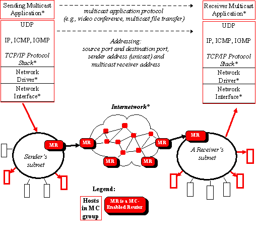
The above diagram only shows the direction of multicast datagrams, and NOT the traffic needed to communicate host group membership and routing infomration.
Multicast Filtering Switches
The default behaviour for a Layer 2 switch would be to forward all multicast traffic to every port that belongs to the destination on the LAN switch. This would defeat the purpose of the switch, which is to limit traffic to the ports that need to receive the data.
IP Multicast can be optimised in a LAN by using multicast filering switches. An IP Multicast aware switch provides the same benefits as a Multicast Router, but wihhin the local area network. Without one, the multicast traffic is sent to all segments onthe local subnet and flood the network with unwanted traffic. An IP Multicast aware switch can automatically set up multicast filters so the multicast traffic is only directed to the partcipateing end nodes.

IGMP Snooping is a method by which multicast is dealt with in a layer 2 environment efficiently. It requires the LAN switch to examine, or 'snoop' some Layer 3 information in the IGMP packets sent between the hosts and the router. When the switch hears the IGMP Host Report from a host for a particular muticast group, the switch adds the host's port number to the associated multicast multicast table entry. When the switch hears the IGMP Leave Group message from a host, it removes the host's port from the table entry.
Since IGMP control messages are transmitted as multicast packets, they are indistinguishable from multicast data at Layer 2. A switch running IGMP Snooping muyst examine every multicast data packet to check if it contains any pertinent IGMP control information.If IGMP Snopping is implemented on a low end switch with a slow CPU this could have sever performance impact when the data is tranmitted at high rates. The solution is to implement IGMP Snooping on high-end switches with special ASIC;s that can perform the IGMP checks in hardware.
Multicast Process
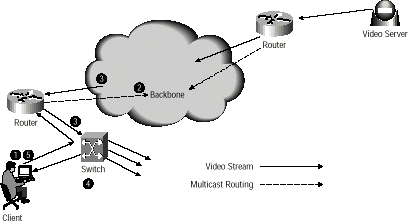
This figure illustrates the process whereby a client receives a video multicast from the server.
1. The client sends an IGMP join message to its designated multicast router. The destination MAC address maps to the Class D address of group being joined, rather being the MAC address of the router. The body of the IGMP datagram also includes the Class D group address.
2. The router logs the join message and uses PIM or another multicast routing protocol to add this segment to the multicast distribution tree.
3. IP multicast traffic transmitted from the server is now distributed via the designated router to the client's subnet. The destination MAC address corresponds to the Class D address of group
4. The switch receives the multicast packet and examines its forwarding table. If no entry exists for the MAC address, the packet will be flooded to all ports within the broadcast domain. If a entry does exist in the switch table, the packet will be forwarded only to the designated ports.
5. With IGMP V2, the client can cease group membership by sending an IGMP leave to the router. With IGMP V1, the client remains a member of the group until it fails to send a join message in response to a query from the router. Multicast routers also periodically send an IGMP query to the "all multicast hosts" group or to a specific multicast group on the subnet to determine which groups are still active within the subnet. Each host delays its response to a query by a small random period and will then respond only if no other host in the group has already reported. This mechanism prevents many hosts from congesting the network with simultaneous reports.
Dynamic Registration
Whereas an IP unicast address is statically bound to a single local network interface on a single IP network, an IP host group address is dynamically bound to a set of local network interfaces on a set of IP networks. An IP host group address is not bound to a set of IP unicast addresses. Multicast routers do not need to know the list of member hosts for each group - only the groups for which there is one member on the subnetwork. A multicast router attatched to an Ethernet need associate only a single Ethernet multicast address with each host group having a local member.
There must be a mechanism that informs the network that the computer is a member of a particular group. Without this information, the network would be forced to flood rather than multicast the transmissions for each group. For IP networks, the Internet Group Multicast Protocol (IGMP) is an IP datagram protocol between routers and hosts that allows group membership lists to be dynamically maintained. The host sends an IGMP "report", or join, to the router to join the group. Periodically, the router sends a "query" to learn which hosts are still part of a group. If a host wants to continue its group membership, it responds to the query with a report. If the host sends no report, the router prunes the group list to minimize unnecessary transmissions. With IGMP V2, a host may send a "leave" message to inform the router that it no longer is participating in a multicast group. This allows the router to prune the group list before the next query is scheduled, minimizing the time period in which wasted transmissions are forwarded to the network.
Session Directroy (SDR)
The SDR tool, which is part of the MBONE network, allows multimedia multicast sessions to be created by other users in the network. These sessions are announced by the SRT application via well known multicast groups.
Dynamic assignment of the group address used for multicast was typically accomplised by using this application. It would detect collisions in IP multicast group address assignment at the time new sessions were being created and pick an unused address. While this was sufficient for use on the old MBONE when the total number of multicast sessions were few, SDR has sever scaling problems that preclude it from contiuing to be used as the number of session increases.
Multicast Address Set-Claim (MASC)
This is a dynamic technique under consideration that is being developed by the 'malloc' Working Group of the IETF. This new proposal will provide for dynamic allocation of the global IP Multicast address space in a hierarchical manner. Under this scheme, domains 'lease' IP Multicast group address space from their parent domain. These leases are good only for a set period. It is possible that the parent domain may grant a completely different range at least renewal time due to the need to reclaim address space for use elsewhere on the internet.
Static Group Address Assignment
Until MASC is up, one has to use static multicast address allocatioin. The basic concept is that we use the 233/8 address space for static address allocation, in which the middle two octets of the group address containing your AS number. The final octet is then available for group assignment.
See draft. draft-ieft-mboned-glob-addressing-xx.txt.
Time to Live (TTL)
Each IP Multicast packet uses a TTL field of the IP header as a sope limiting parameter to control the number of hops that an IP multicast packet is allowed to propogate. Each time a router forwards a packet, its TTL is decreases. Should the TTL packet be expired (TTL 0), it is dropped, without notification to the sender. This mechanism prvents the messages from needeless transmission to regions fo the worldwideinternet that lie beyond the subnets containing the multicast group members.
A local network multicast reaches all immediate neighbouring members of the destination host group as the TTL is set to 1 by default. If the IP Multicast packet has a TTL greater than 1, then the multicast router(s) attatched to the local network takes responsibility for the internetwork forward.
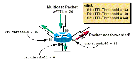
TTL thresholds in multicast routers prevent datagrams with less than a certain TTL from traversing certain subnets. This can provide a convient mechanism for confining mulicast traffic to within the campus or enterprise network.
Multicast Forwarding
Most IP multicast applications are based on UDP, which uses "best effort delivery" and lacks the congestion avoidance windowing mechanism of TCP. As a result, multicast packets may be dropped more often than unicast TCP packets. Since it is not practical for real-time applications to request retransmissions, audio and video broadcasts may suffer degradation due to packet drops. Prior to the deployment of quality of service (QoS), the best way to minimize lost packets in frame-based networks is to provision adequate bandwidth, especially at the edge of the network. The reliability of multicast transmissions will be improved when the ReSerVation Protocol (RSVP), the Real-Time Transport Protocol (RTP), and 802.1p or other Layer 2 priority mechanisms make it possible to deliver end-to-end QoS over a Layer 2/Layer 3 network.
Multicasting Routing Concepts
| IP Routing |
When the source of a message sends a message from one subnet to the destination located on another subnet, there must be someway of determining how to get from the source to the destination. This is the function of the IP protocol. Each host on the internet has an address that identifies the particular host on that subnet. Routers periodically send routing update messages to adjacent routers, conveying the state fo the network as perceived by that particular router. This information is recorded in IP routing tables that are then used to determine optimal transmission paths for forwarding messages across the network. In unicast, the process of directing the datagrams to the destination is relatively straight forward due to the single physical location of the destination host as it is bound to a single address. |
| Multicast Routing |
A multicast address identifies a particular tranmission session rather than a specific physical destination host. This ensures that an individual host is able to join an ongoing multicast session. This desire is usually communicated through the use of IGMP. A naive approach would be for multicast transmissions would be for the sending host (source) to maintain table identifying all the rceiving subnets participating in the session and not to send a separate copy of the data to each receivng subnet. This should be extremely resource hungry, as many of the data streams would follow the same path throughout the network. The technique in use to combat this bandwidth waste is to involve the network routers such that they can translate the multicast addresses into hosts addresses. The basic principle is that in mulitcast routing, the routers interact with each other to exchange information about neighbouring routers. To avoid duplication of effort, a single router is selected (via IGMP) as the Designated Router (DR) for each physical network. |
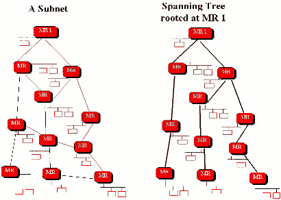
| Spanning Trees |
In order to tranmit the multicast transmission efficiently, Designated Routers construct what is known a Spanning Tree that connects all members of an IP mulitcast group.
A spanning tree is constructed such that there is just enough connectivity so that there is only one path between every pair of routers, and is loop-free. ie distribution trees construction is to ensure that at most, one copy of each packet is forwarded on each branch of the tree. If each router knows which of its lines belong to the spanning tree, it can copy an incoming multicast datagram onto all of its outgoing branches, generating only the minimum needed number of copies, replicating messages only when the tree branches. This mininises the number of copies of the messages that are transmitted through the network. As the multicast groups are dynamic, with members leaving or joining at any time, it is also necessary for the spanning tree to be dynamically updated. Braches on which there are no 'listeners' must be discarded (pruned). A router selects a spanning tree based on the network layer source address of a multicast packet and prunes that spanning tree based on the network layer destination address. The spanning tree algorithm used and how multicast routers interact depends on the objectives of the routing protocols. |
| DM & SM |
IP Multicast routing algorithms follow one of two basic approaches; Dense-mode (DM): DM protocols assume that multicast group members are densely distributed throuhgout the network and that bandwidth is plentiful. As such, almost all routers in the network will need to distribute multicast traffic for each multicast group (for example, almost all hosts on the network belong to each multicast group). Accordingly, DM builds distribution trees by initially flooding the entire network and then pruning back the small number of paths without receivers. Dense Mode protocols include Distance Vector Multicast Routing Protocol (DVMRP), Multicast Open Shortest Path First (MOSPF), and Protocol Independent Mutlicast - Dense Mode (PIM-DM) and are most appropriate in LAN environments with densely clustered receivers and the bandwidth to tolerate flooding. Certain protocols use the their own private unicast reachability routing tables: DVMRP uses its own distance vector routing protocol to determine how to build source-based distribution trees. Similarly, MOSPF, uses its own link state database to build source-based distribution trees. Sparse-mode (SM): SM protocols assume that relatively few routers in the network will be involved in each multicast and that bandwidth is relatively small. The hosts belonging to the group are widely dispersed, as might be the case for most multicasts in the Internet. Therefore, SM protocols begin with an empty distribution tree and add branches only as the result of explicit requests to join the distribution through using unicast forward table information. The SM protocols, Core Based Trees (CBT) and Protocol Independent Multicast - Sparse Mode (PIM-SM), are generally more appropriate in WAN environments. PIM is also capable of functioning in Sparse-Dense mode by adjusting its behavior to match the characteristics of each receiver group. |
Multicast Standards
In order to scale the possibility of multicasting, protocols are needed to scale multicasting globally. These are known as routing standards.
| Standard | Description |
| PIM |
Protocol Indepent Multicast is optimised for internetworks with many data streams but relatively few number of LANs. By defining a rendez-vous point that also used as a registration point, it facilitates the routing of packets. When multicast traffic is sent, the router that is nearest to the source point sends data to the rendez-vous point. When a client wishes to receive the multicast, the last-hop router (with respect to the client) registers with the rendez-vous point. A data stream then flows from the sender to the rendez-vous point and then to the receiver. Routers in the path optimise the path and automically remove any unessary hops, even at the rendez-vous point. |
| MOSPF | The Multicast Open Shortest Path First is an extension of oSPF and hence only works in networks that incorporates OSPF and where there is only a small number of multicast groups. It employs a unicast routing protocol so that every router is away of all available links. It calculates routes for each source/multicast group pait when the router recieves traffic for that pair and the route is cached until a topology change occurs (if it does happen, it recalcuates the topology). Due to the calculations and caching, this method takes up a lot of CPU bandwidth on the router. |
| Other | Other standards exists such as a suppression system from Cisco that prevents switched ports on a LAN being flooded by a broadcast storm. |
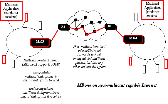
ReCasting and Tunneling
In certains cases, a source or destination may not be attached to a multicast enabled network. One example is when a branch office with multiple receive clients may be connected via WAN to the headquarters. If more than one client at the branch were to request a multicast stream, the nework might attept to multicast the stream at the headquarters (sending multiple copies), rather than one stream and multicasting it at the branch office. An effective solution is to unicast the stream to the branch office and then to multicast the stream at the branch. The latter is done via IP ReCasting. A ReCaster accepts unicast streams and converts them into multicast. This is similar to Tunnelling where a multicast stream is carried within a unicast session.
In the context of multicasting, tunnelling is the encapsulation of multicast packets in an IP datagram (ie a unicast packet) to route through parts of an internetwork, such as the internet, that don't support multicast routing. This is done on the MBONE, with DVMRP. The encapsulation is added on entry to a tunnel and striped off on exit from the tunnel. Hence, tunnelling is useful as a transitional strategy to achieve ful native IP multicast deployment.
Multicast Disadvantages
Multicast is UDP based. As such, it is limited by the UDP protocol. These include,
· Best Effort Delivery - drops in the data stream are to be expected. Multicast applications should not expect reliable delivery of data and should be designed accordingly. Reliable multicast is in development. Requesting retrasmissions of the lost data is not feasible due to the design of multicasting.
· No Congestion Avoidance - unlike TCP, there is no windowing and 'slow-start' mechanisms. This can result in network congestion. If possible, Mulicast applications should attempt to detect and avoid congestion conditions.
· Duplication - Some multicast protocol mechanisms (eg Asserts, Registers and Shortest Path Tree Transions) may result in the occasional generation of duplicate packets. Multicast applications should be designed to take this into consideration.
· Out of Sequency Packets - variaous network events may result in packets arriving out of sequence - as there is no windowing, multicast applications should handle these cases.
More Indepth Descriptions
| Host Extensions for IP Multicasting |
Requirements for using IP Multicasting on IP. here |
| Address Tranlations | Mapping of the lower ISO levels. here. |
| IGMP | Internet Group Management Protocol. here |
| IP Multicast Routing | DVMRP, MOSPF, CBT, PIMs,, Interoperabilty. Here. |
| Connecting Shared Trees | Methods of utiling many RP to connect shared trees. here. |
| Sun, 21 October, 2001 19:30 |
Room D14, High Energy Particle Physics, Dept. of Physics & Astronomy, UCL, Gower St, London, WC1E 6BT