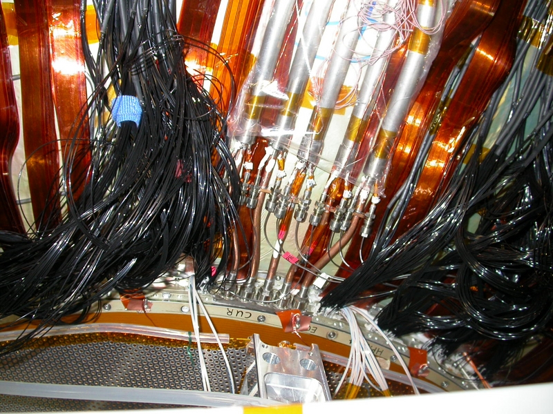
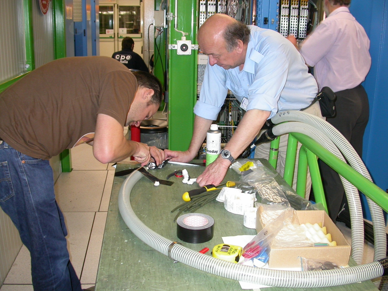
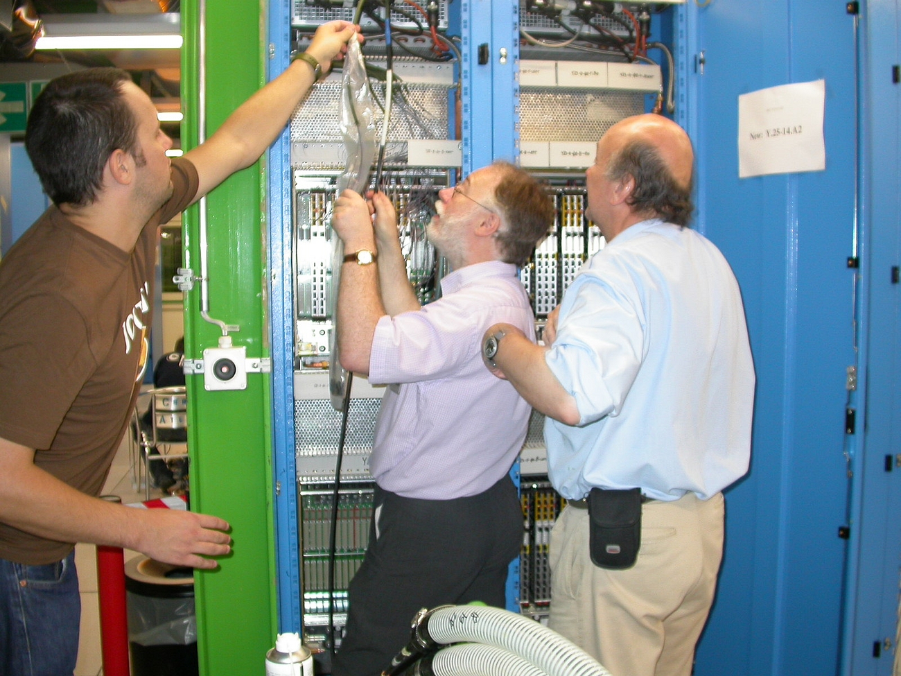
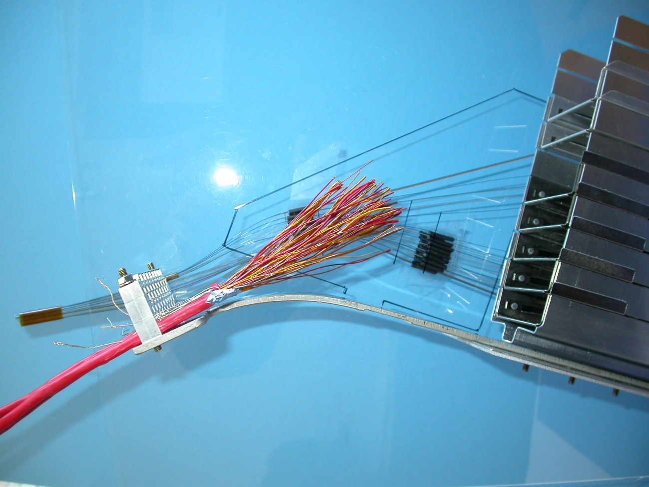
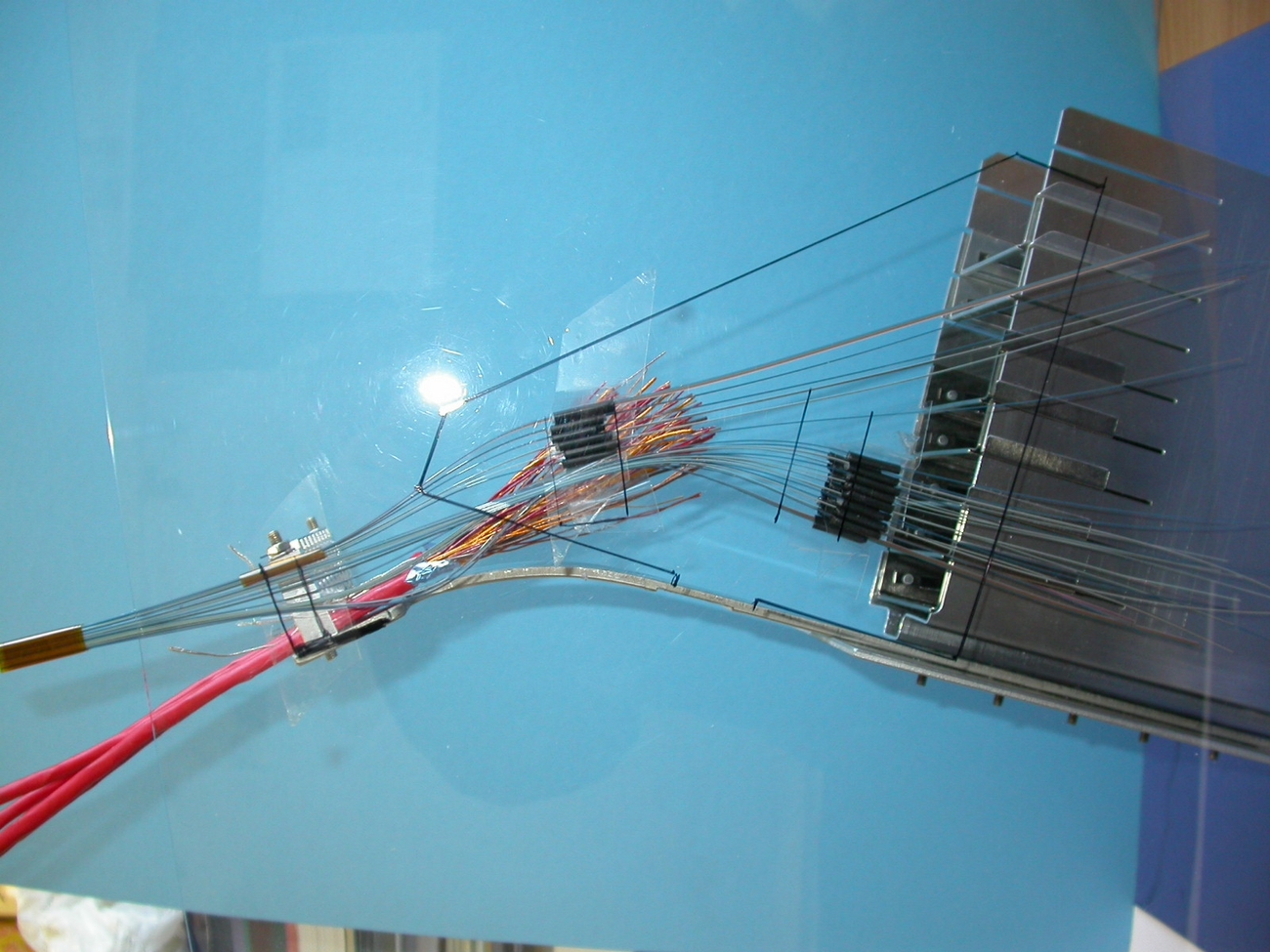
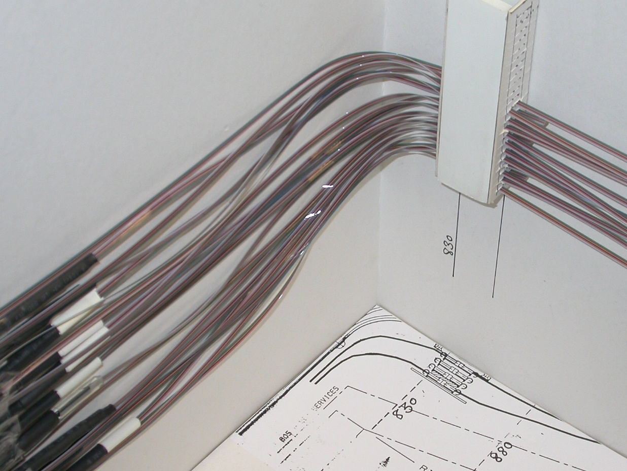
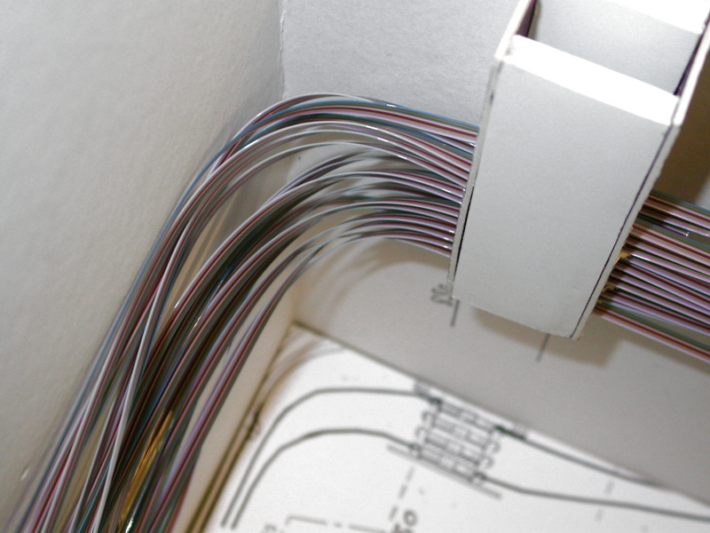
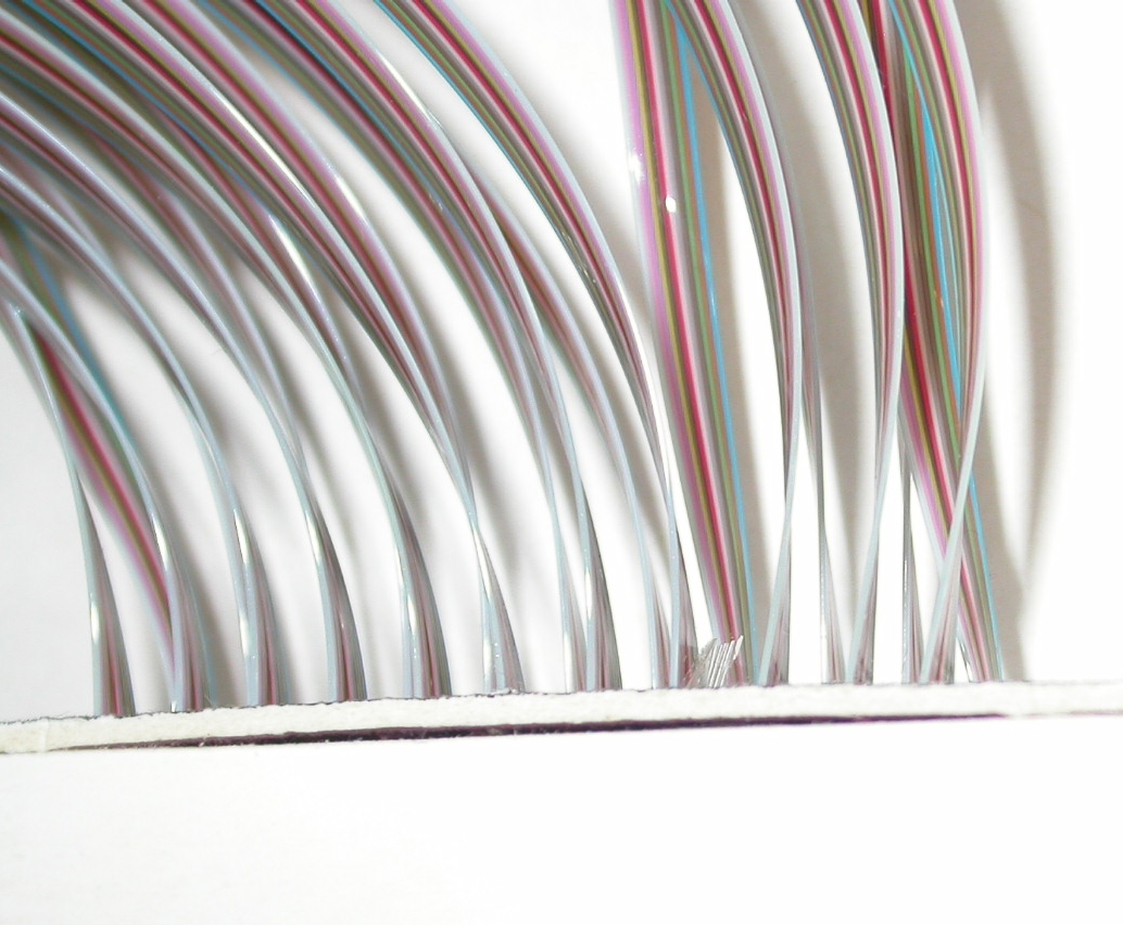
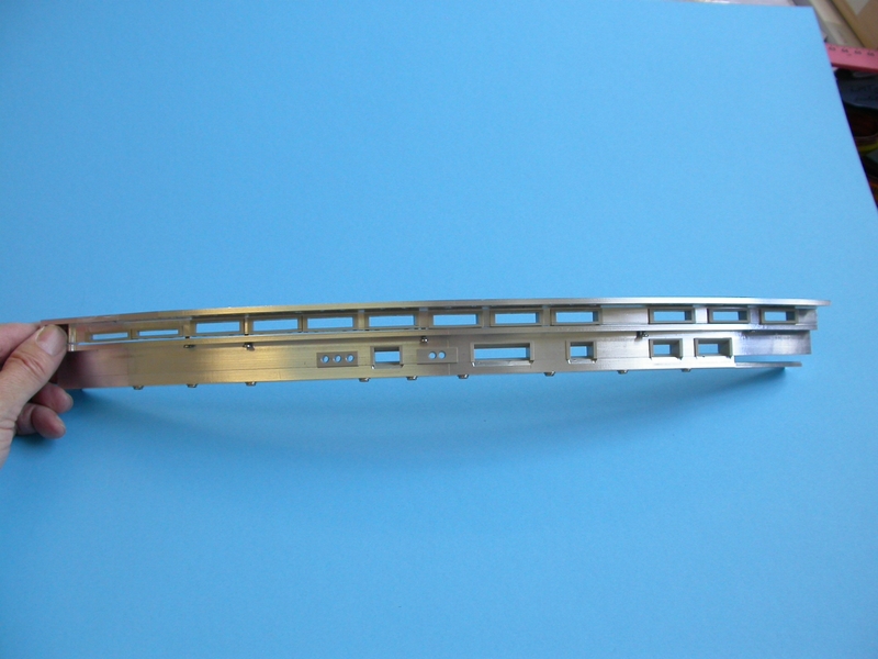
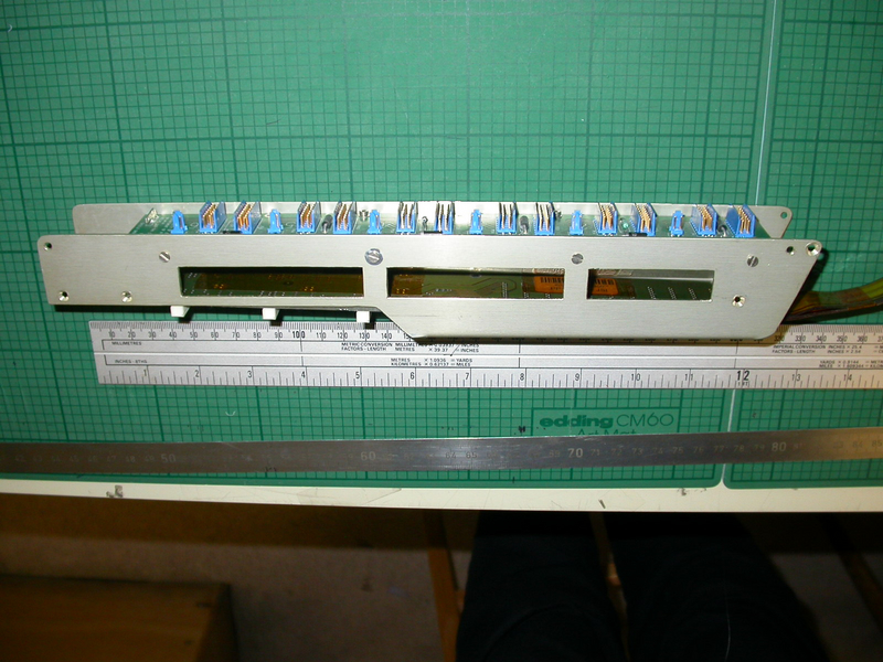
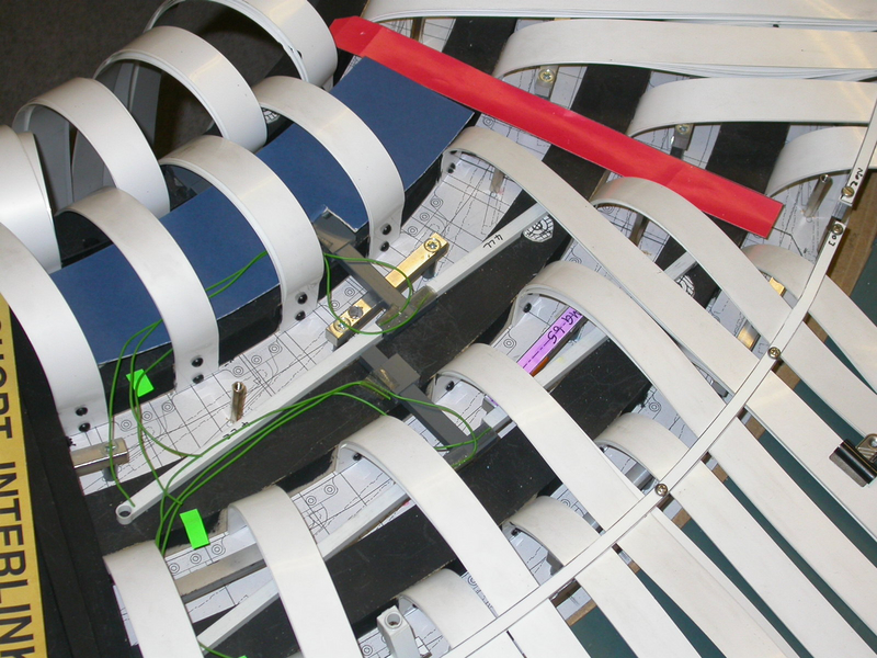
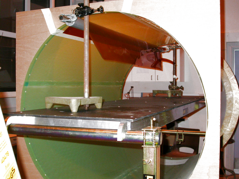
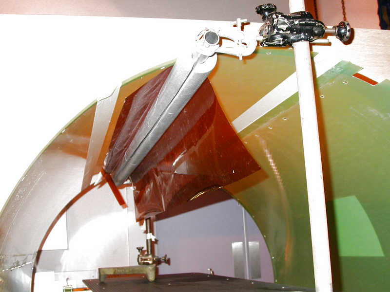
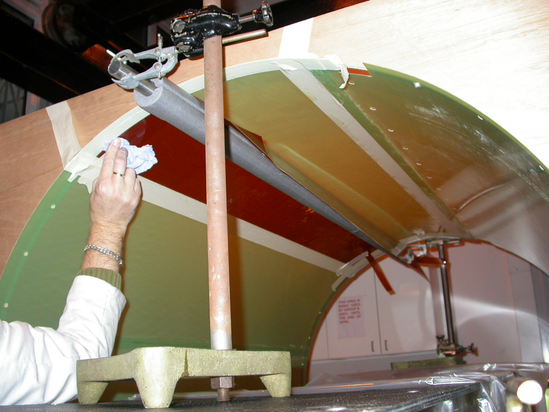
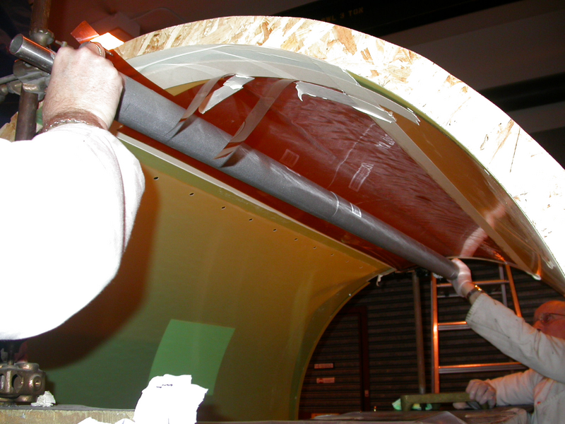
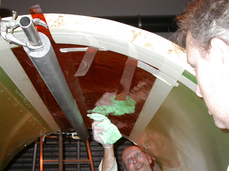
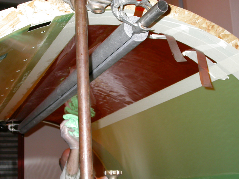
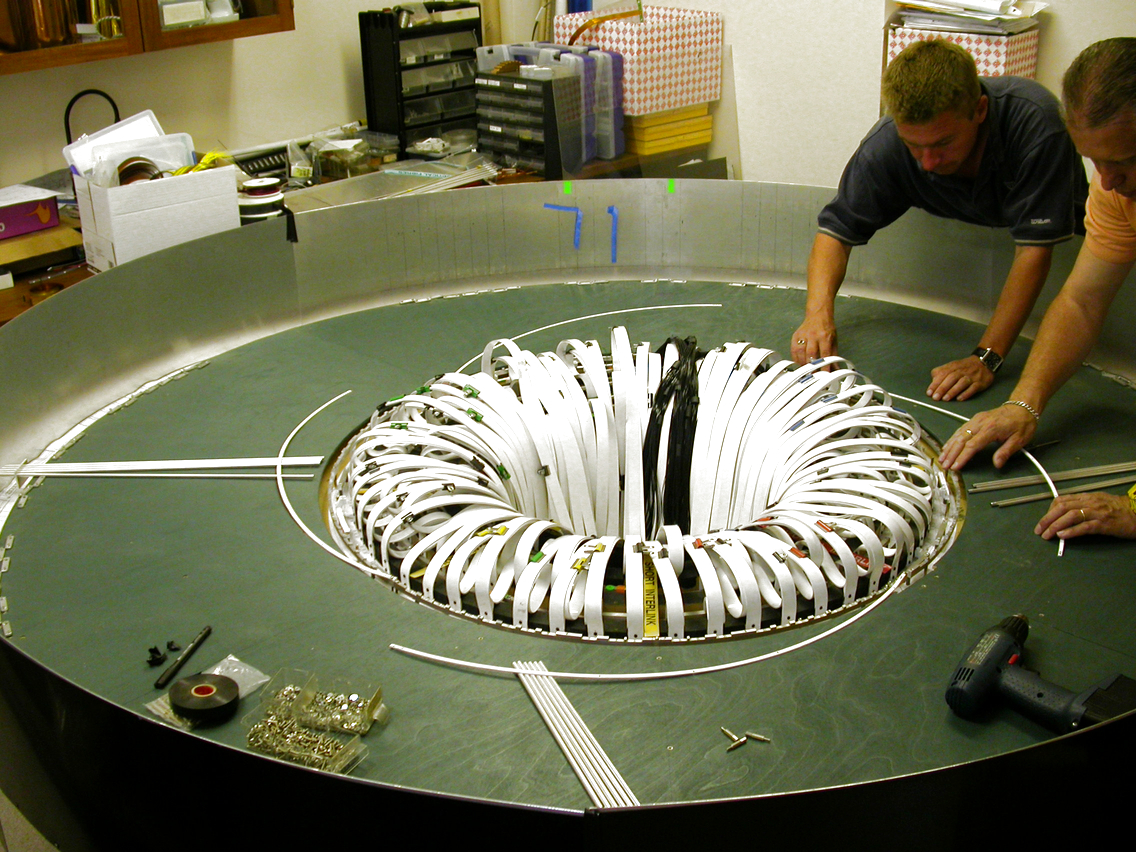
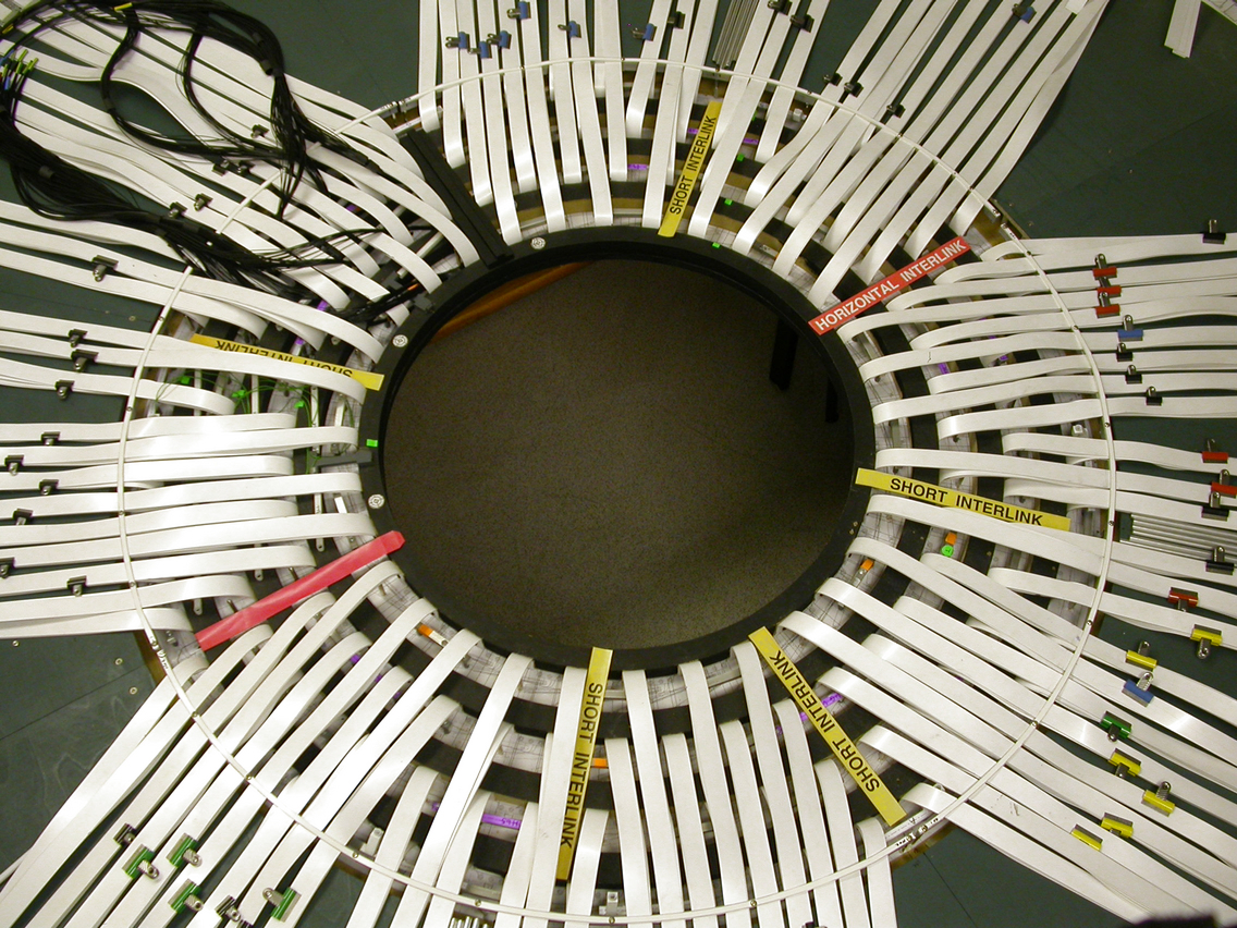
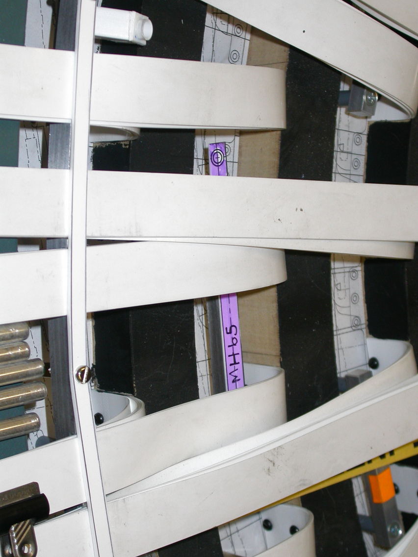
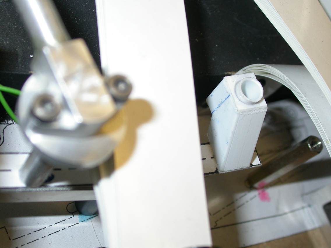
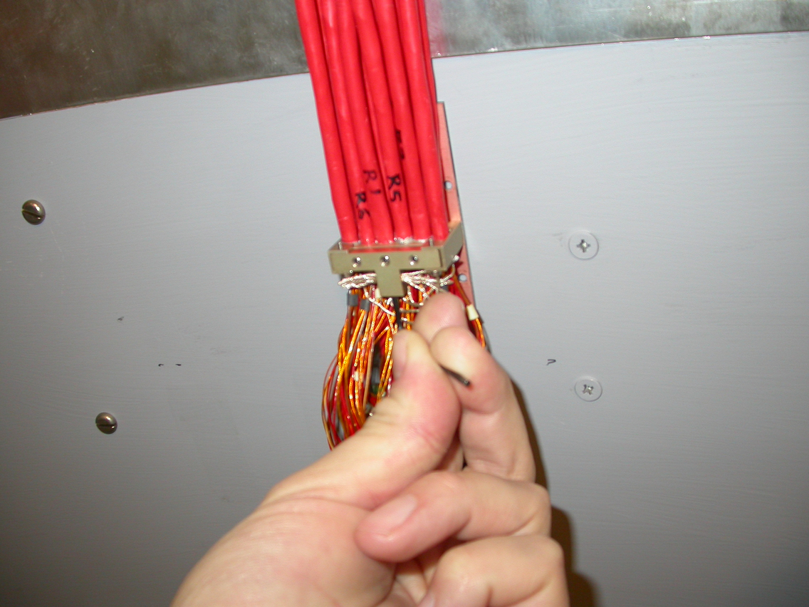
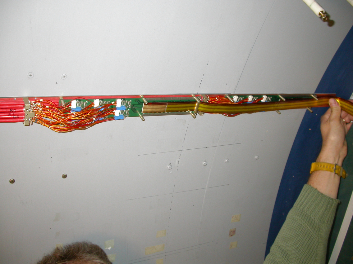
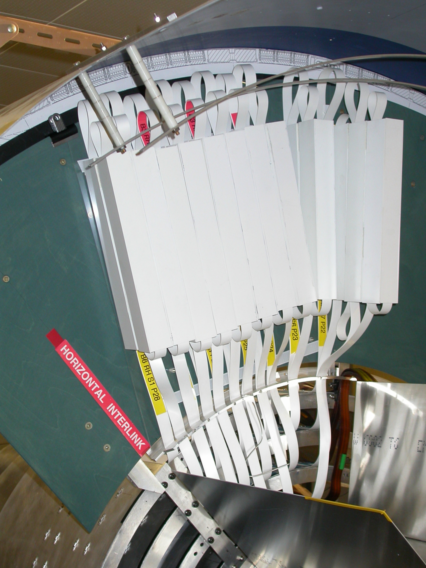
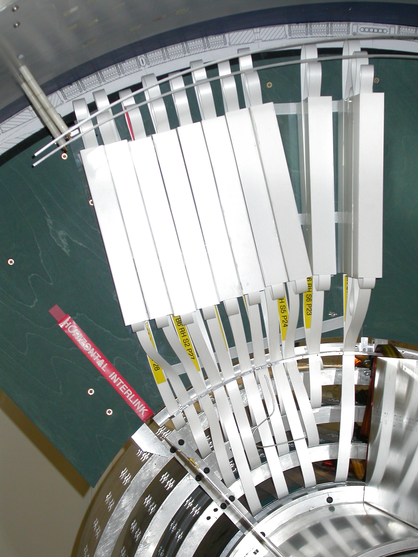
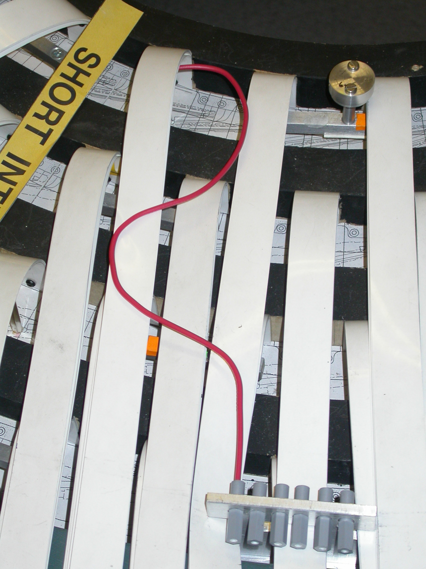
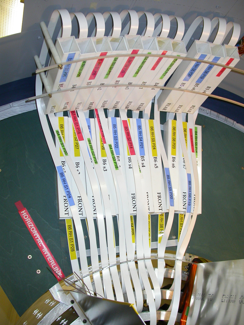
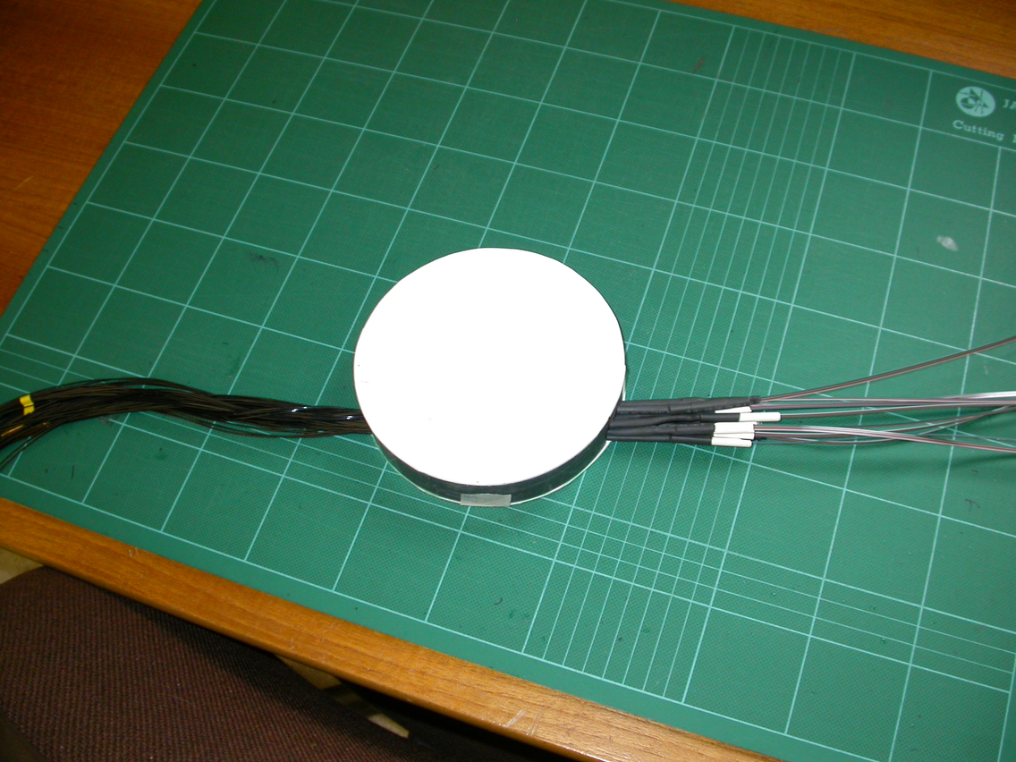
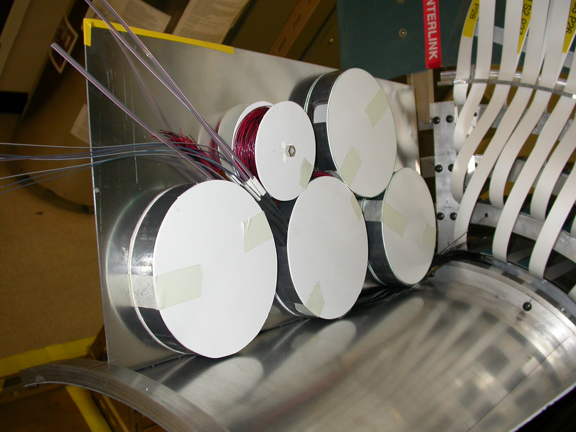
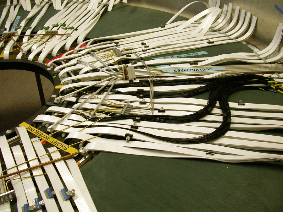
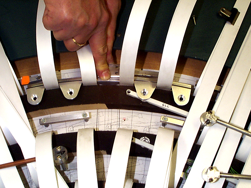
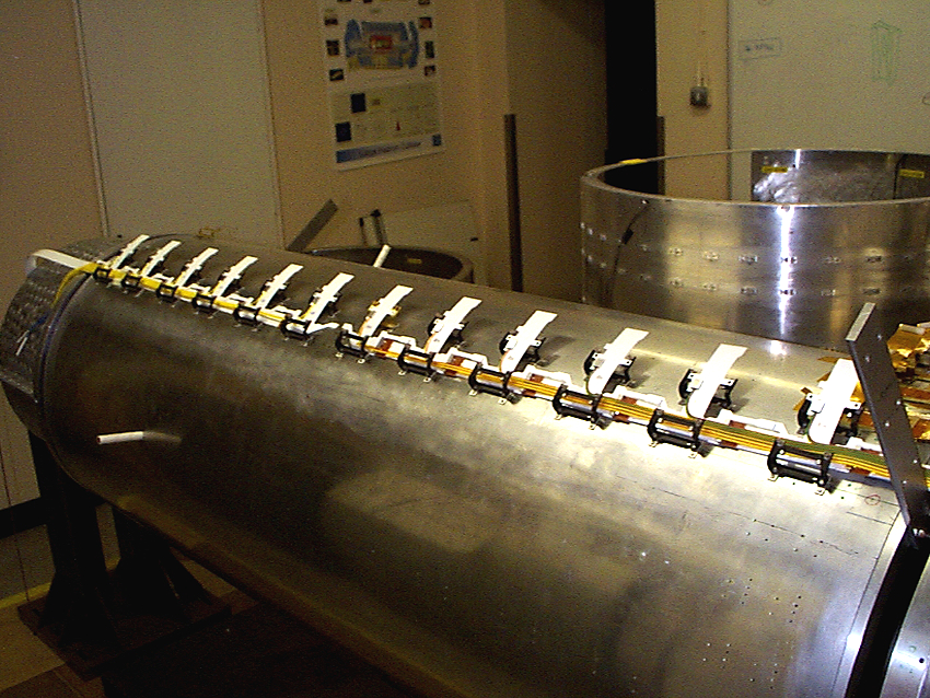
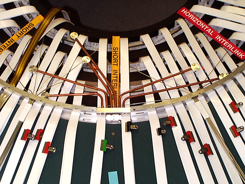
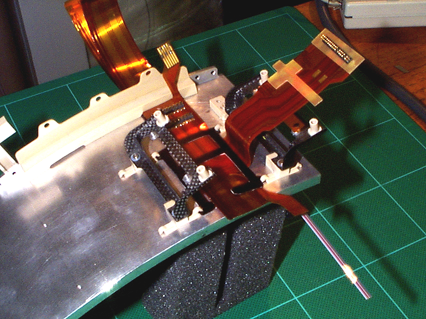
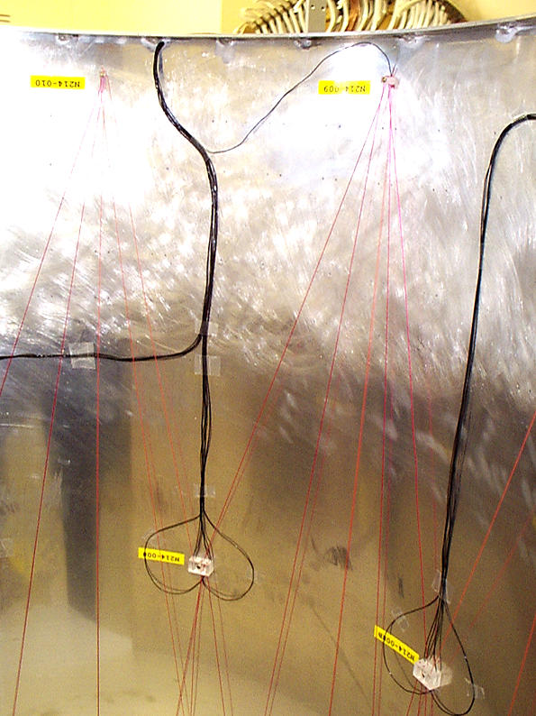
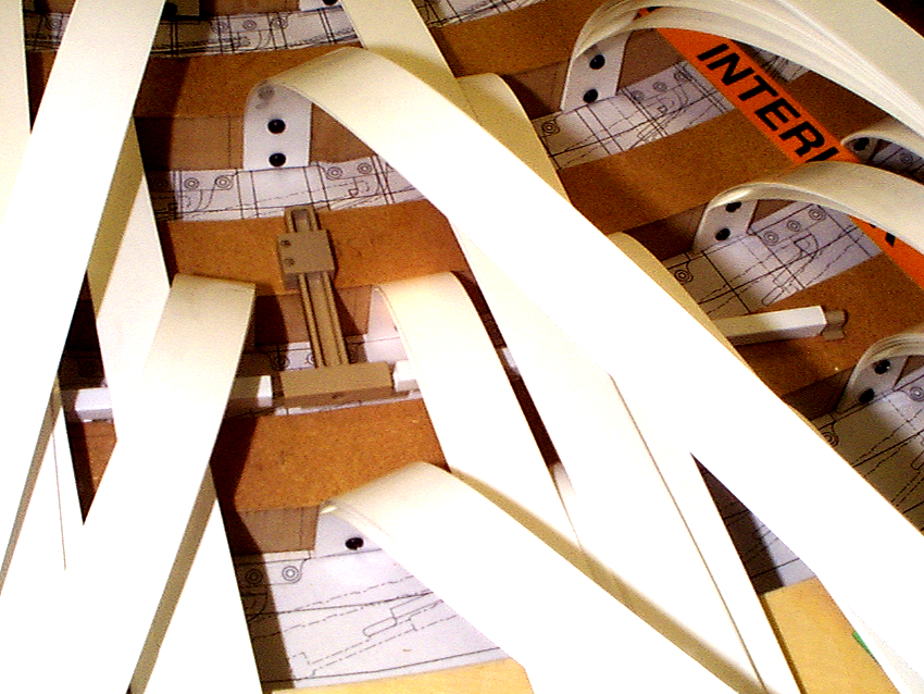
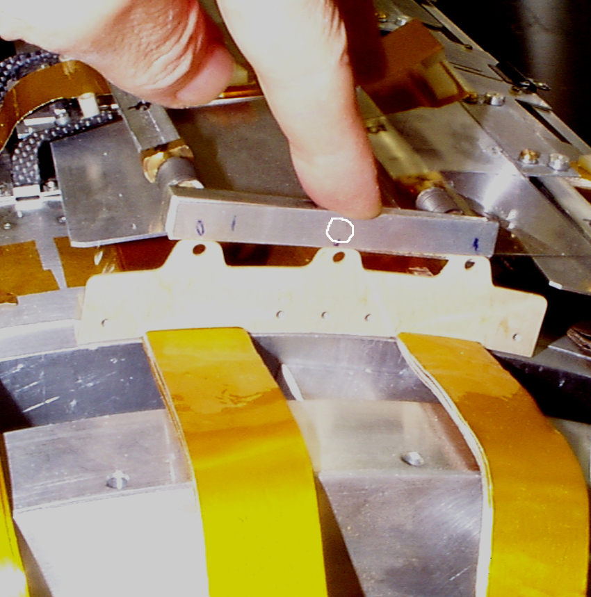
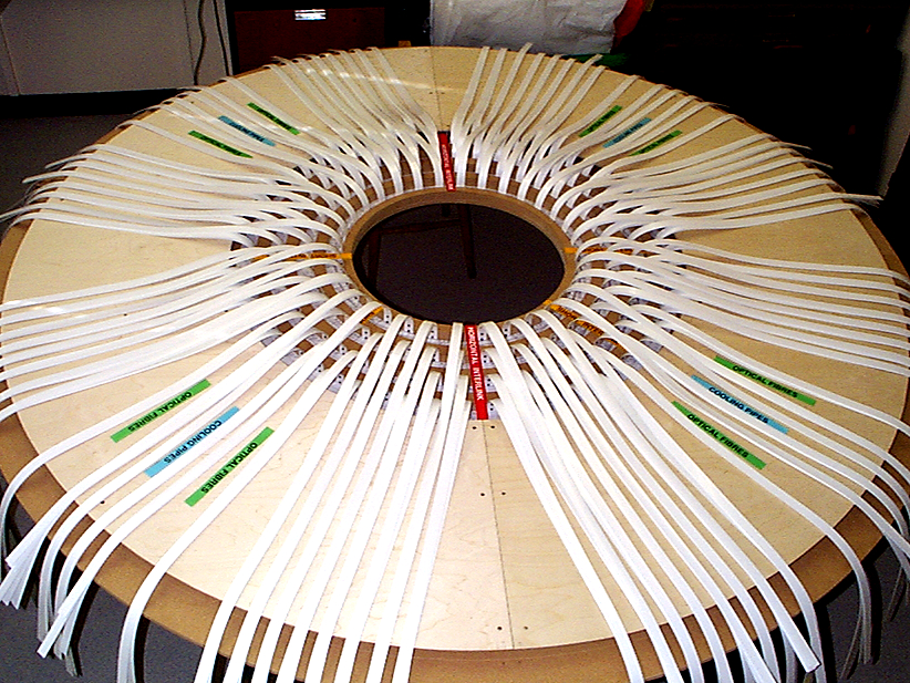
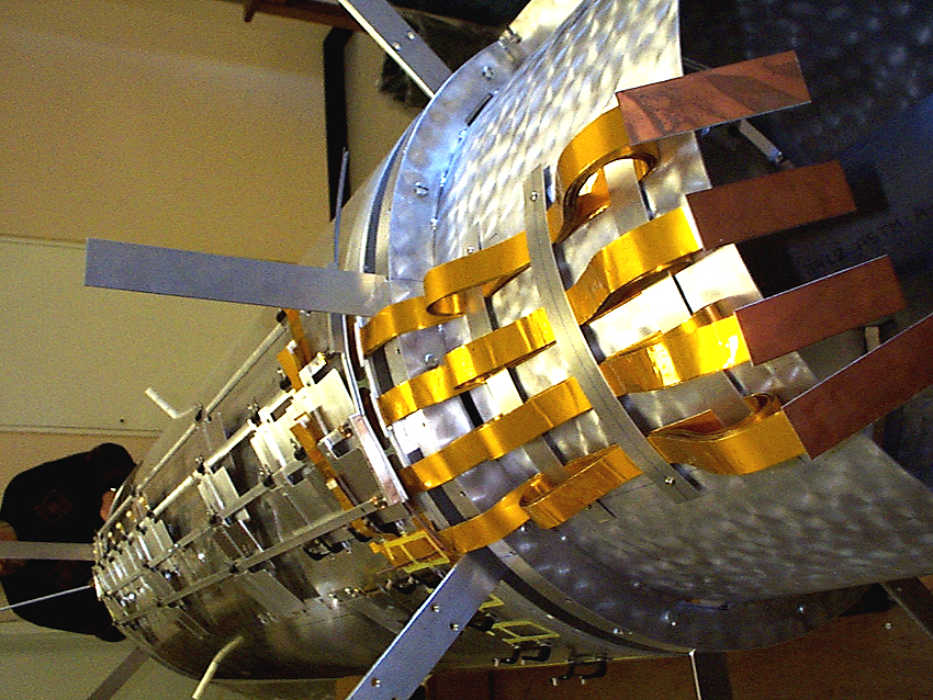
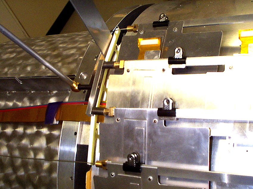
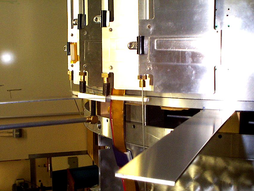
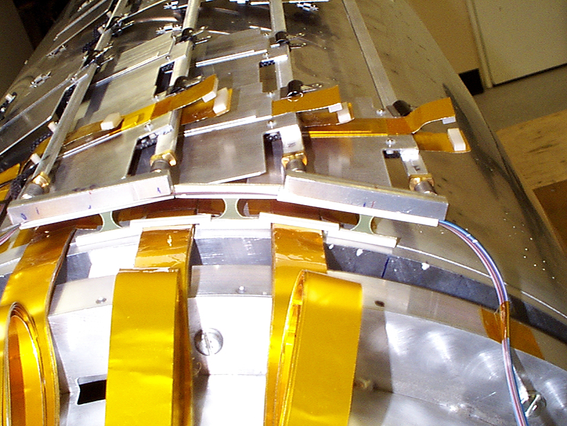
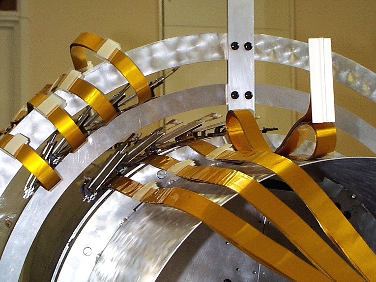
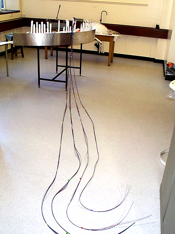
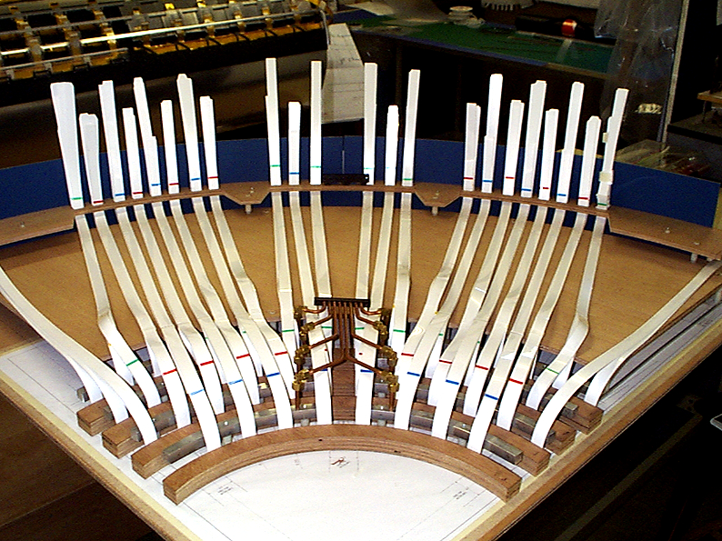
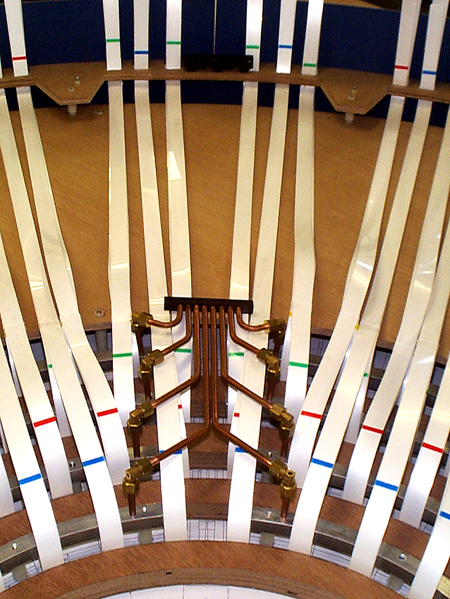
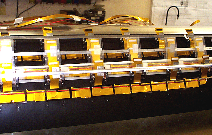
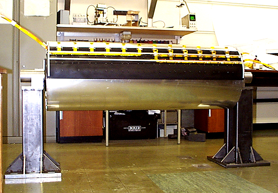
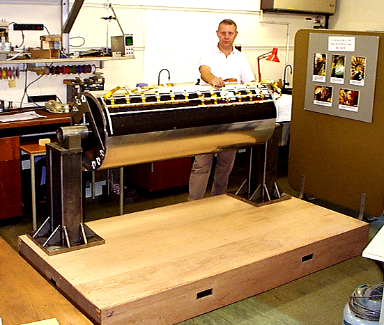
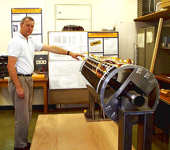
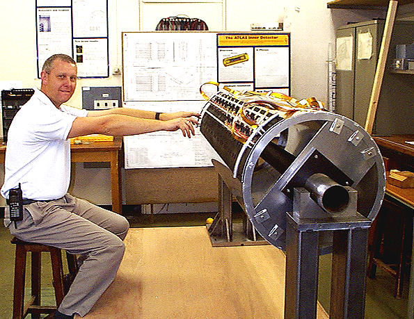
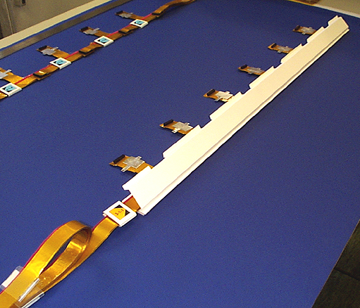
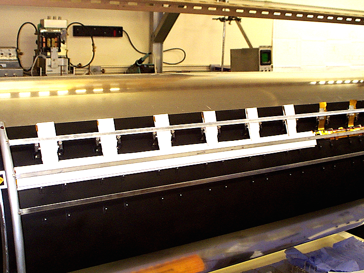
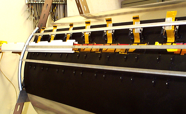
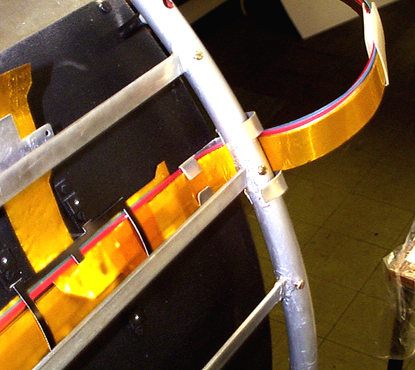
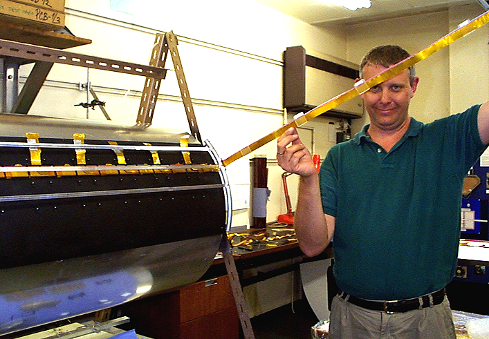
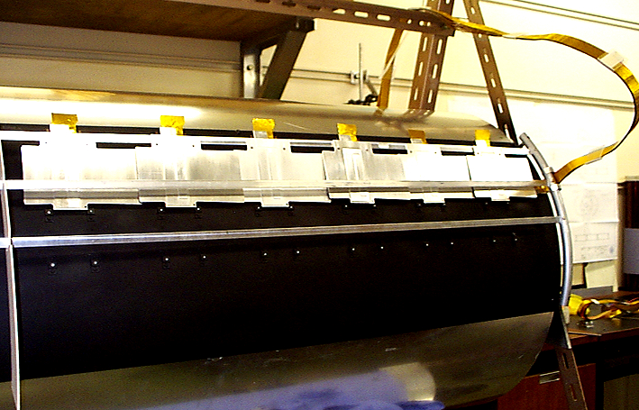
A trial assembly of the LMT PPB1 boards on the support board in situ on the cryostat has been made.
The assembly on the cryostat is of course more difficult than on the bench. It took one and a quarter hours to fit the FRONT and REAR PPB1 boards, fit clamps and connect up the Type II cables. In the real situation the temporary PPB1 boards would have to be removed first. We have found that connecting and disonnecting the Type II cables takes up the most time and has to be done very carefully. Here are some comments as a result of the trial:
1) Marking the connectors so that it is obvious how they should be connected and where will be essential.
2) The various loose components and tools will need to be kept in an 'unspillable' container
3) Very good directional lighting will be needed.
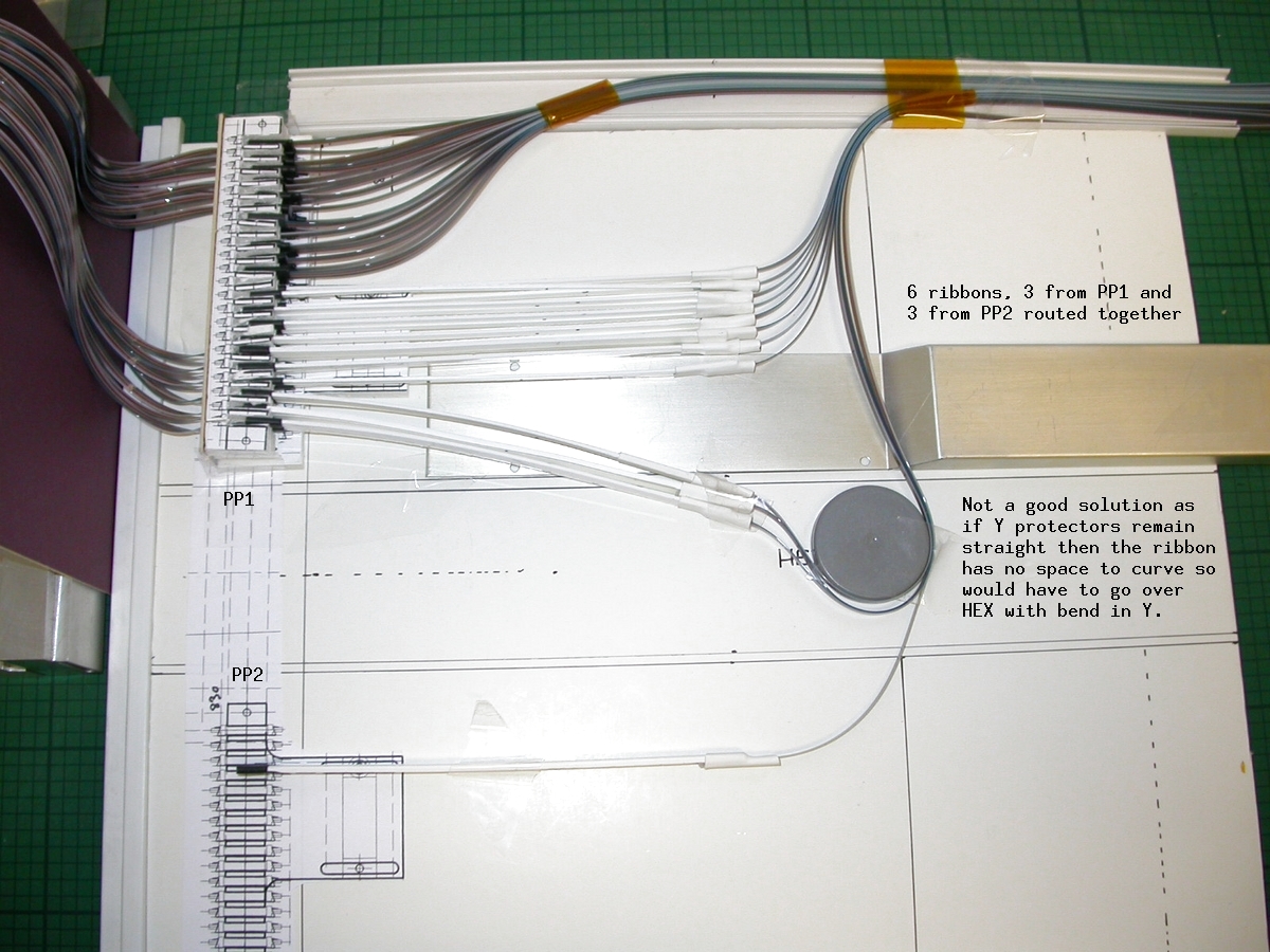
4) The square spacers can probably be modified to allow 6 cables to fit between them and the corners should berounded
5) There should be an additional clamp for the REAR LMTs at the FRONT end of the support board
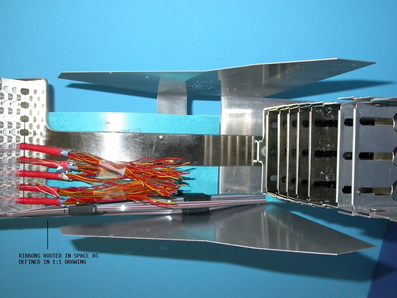
6) The multiple cables should be bunched so that there are no stray cables to get in the way when the adjacent boards are fitted and the final cover fitted.
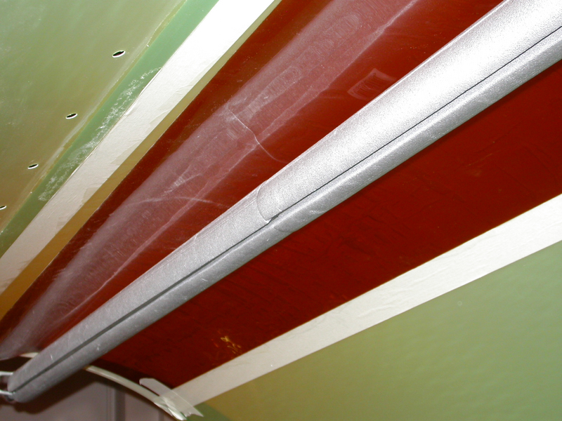
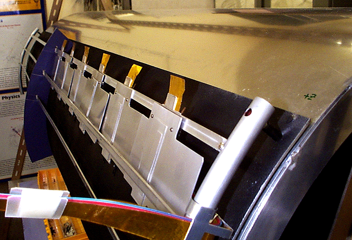
Here are the photos of the trial assembly on the model cryostat at UCL
11/11/2003
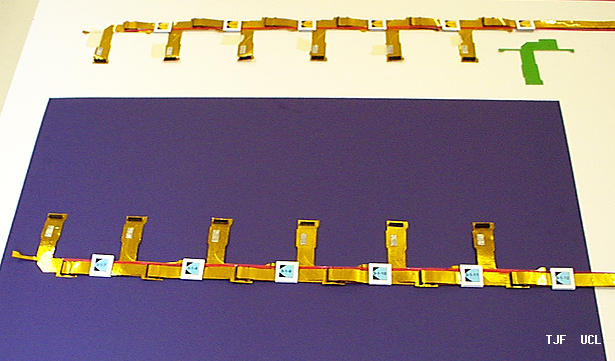
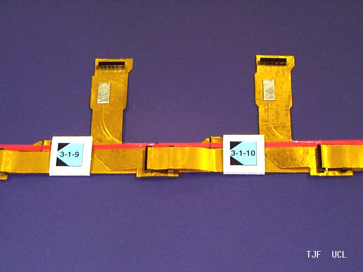
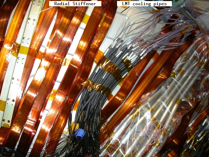
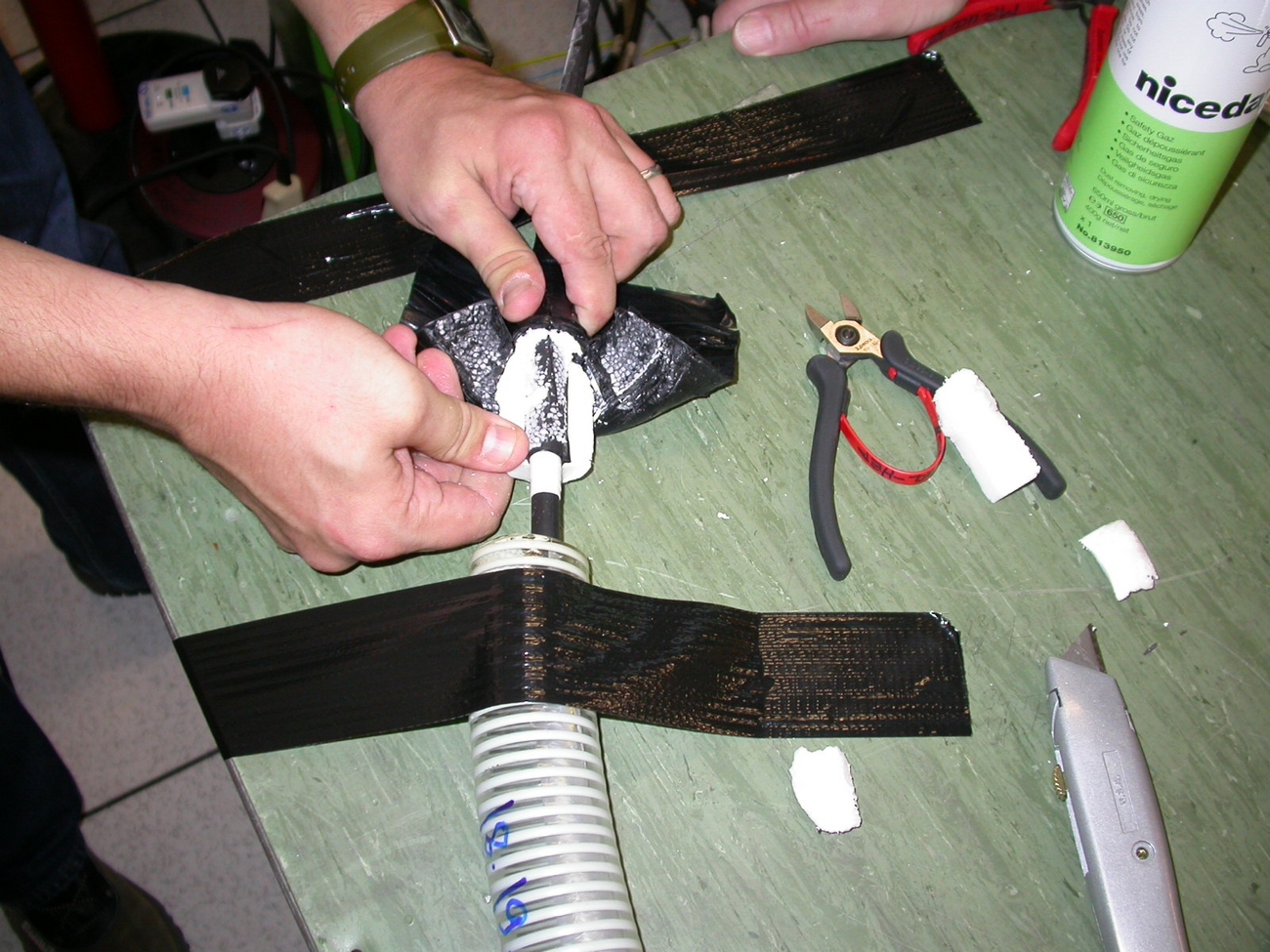
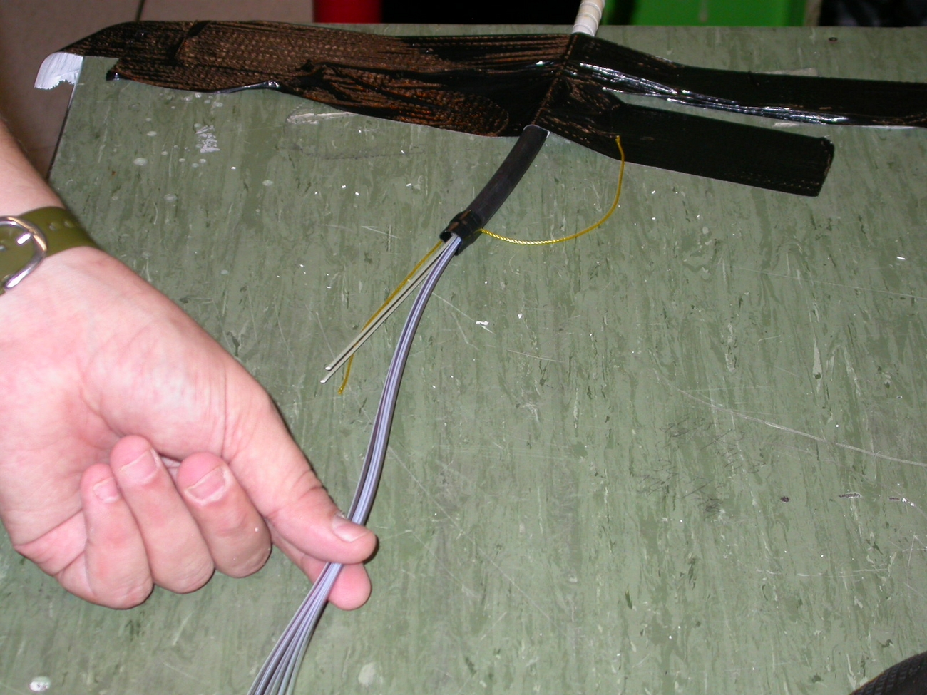
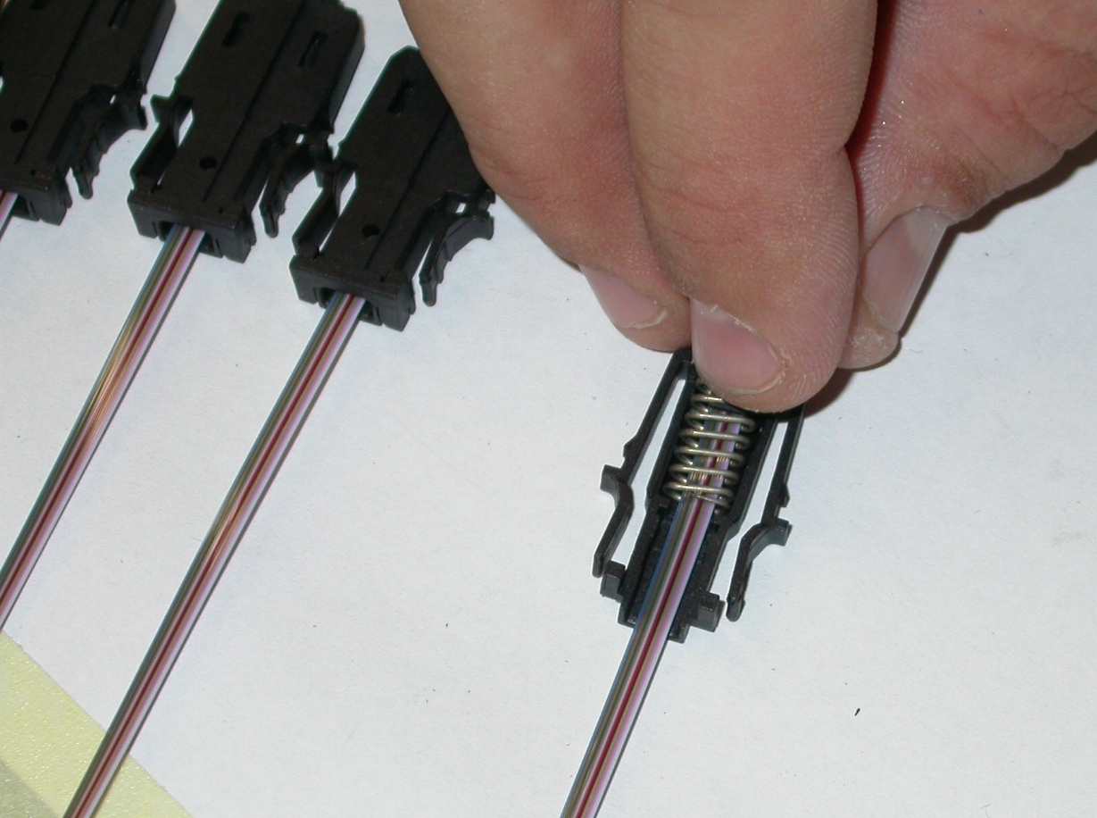
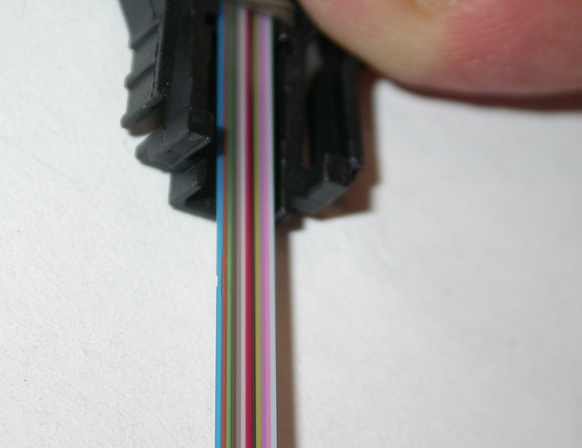
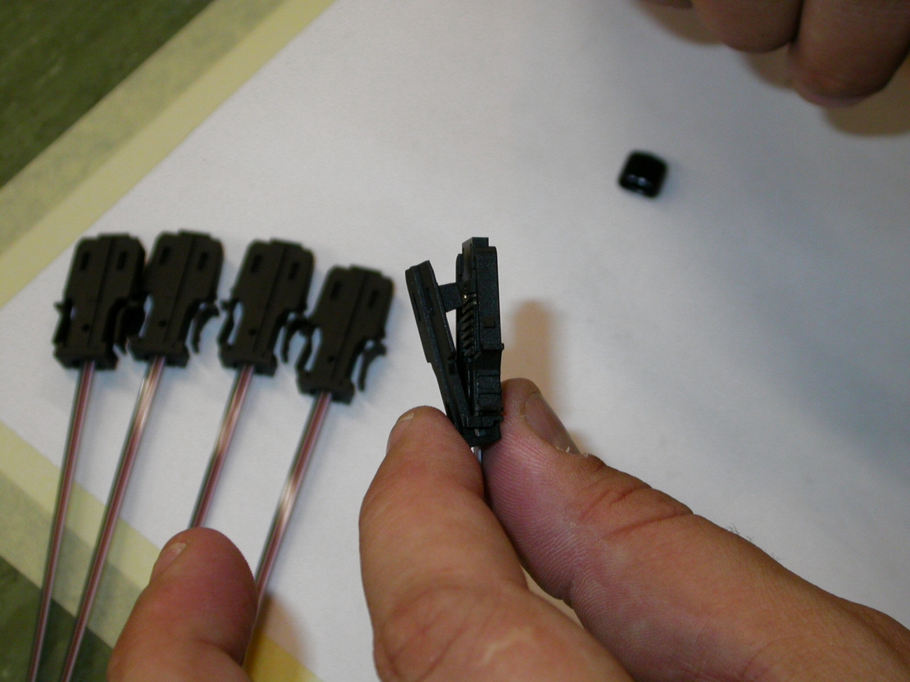
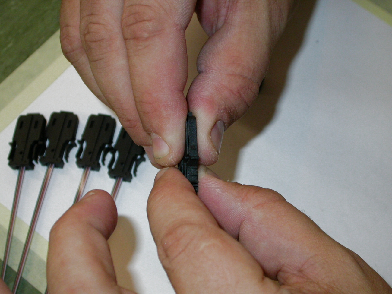
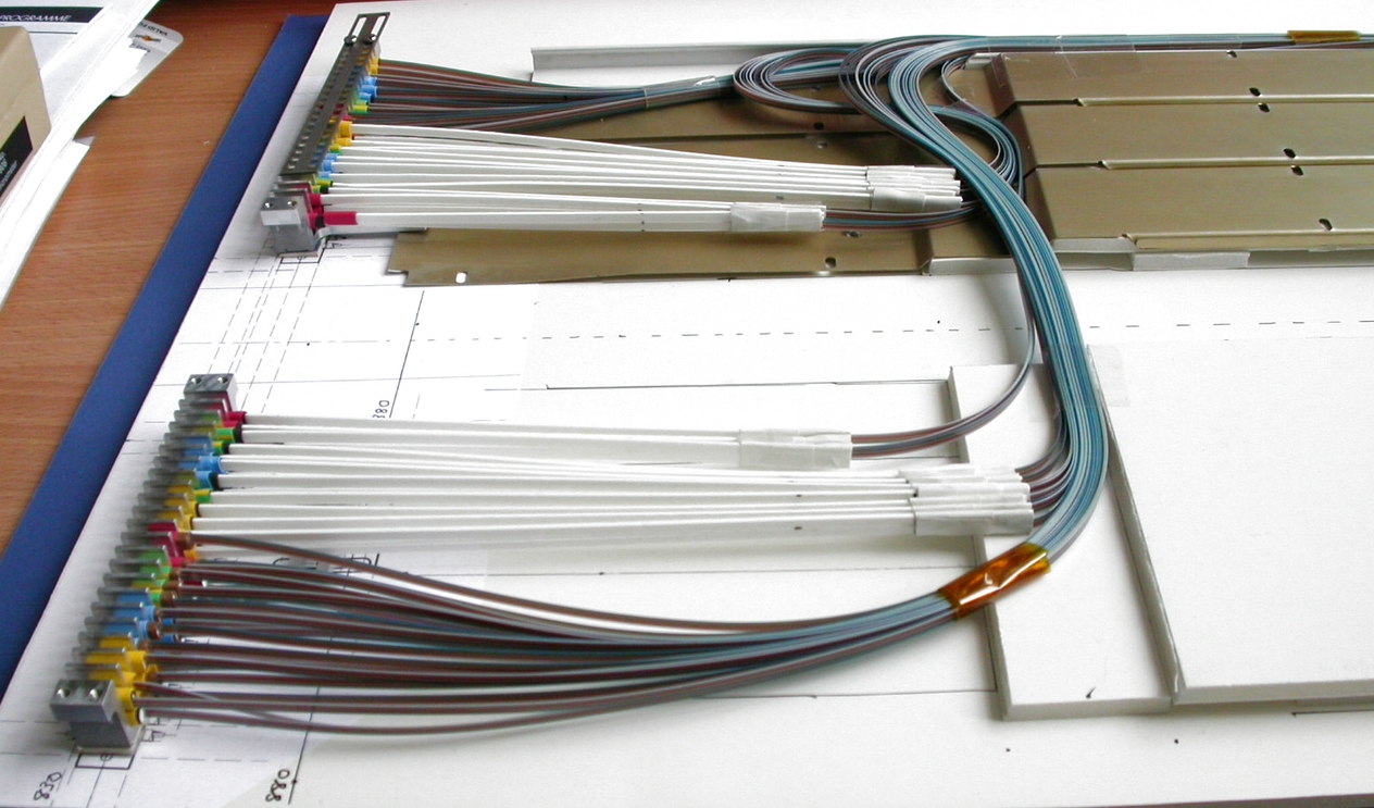
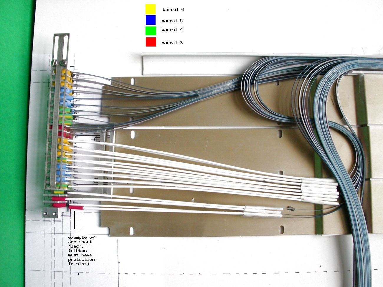
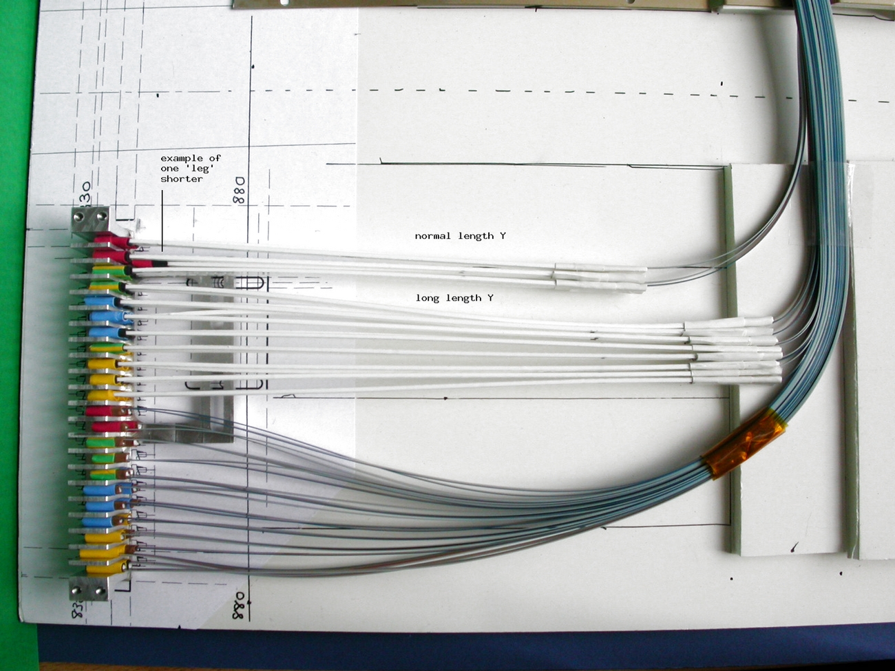
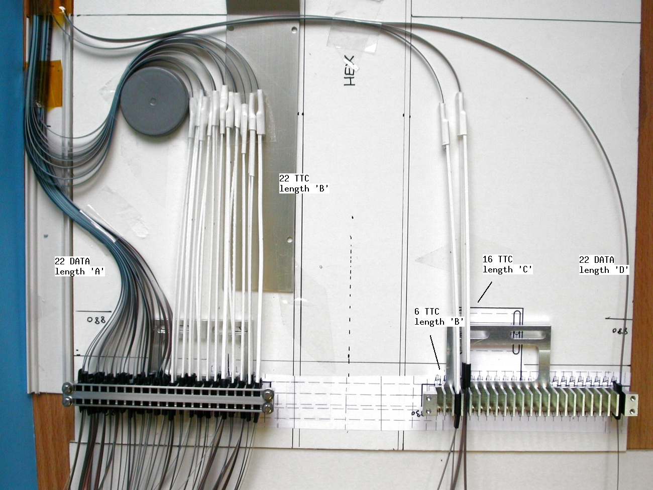
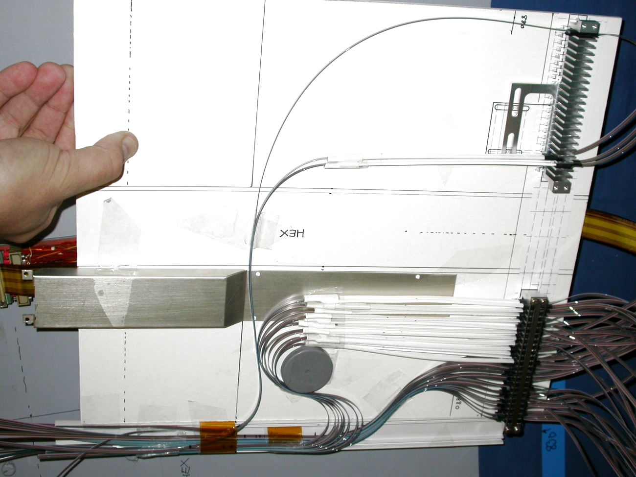
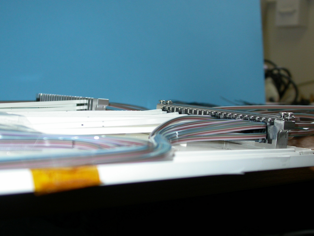
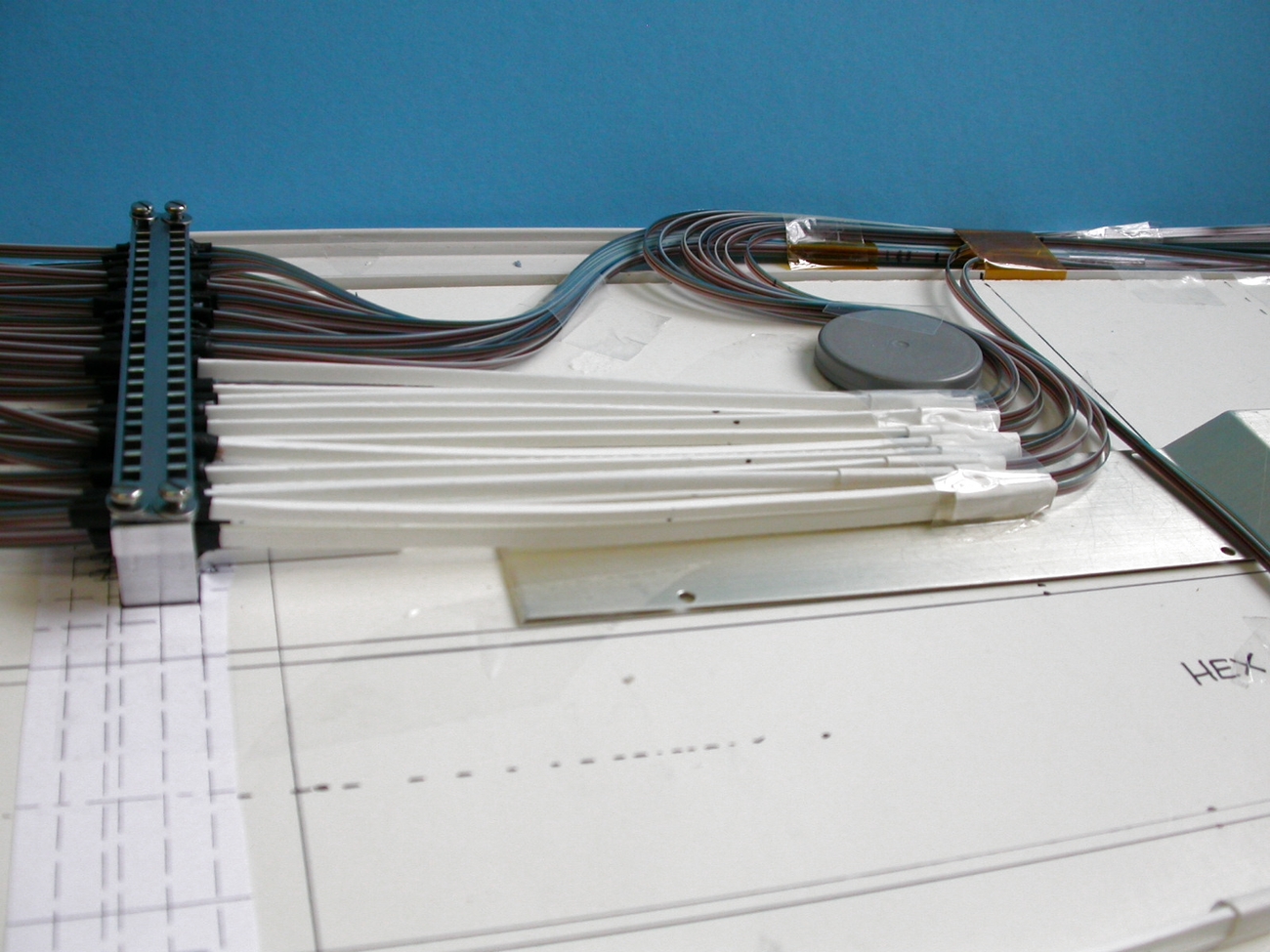
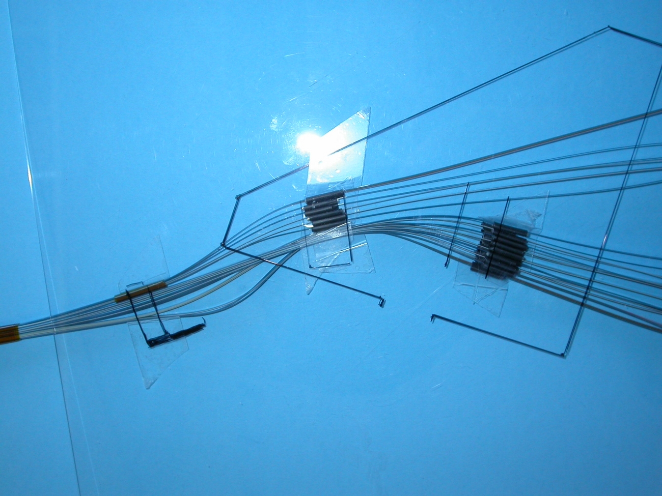
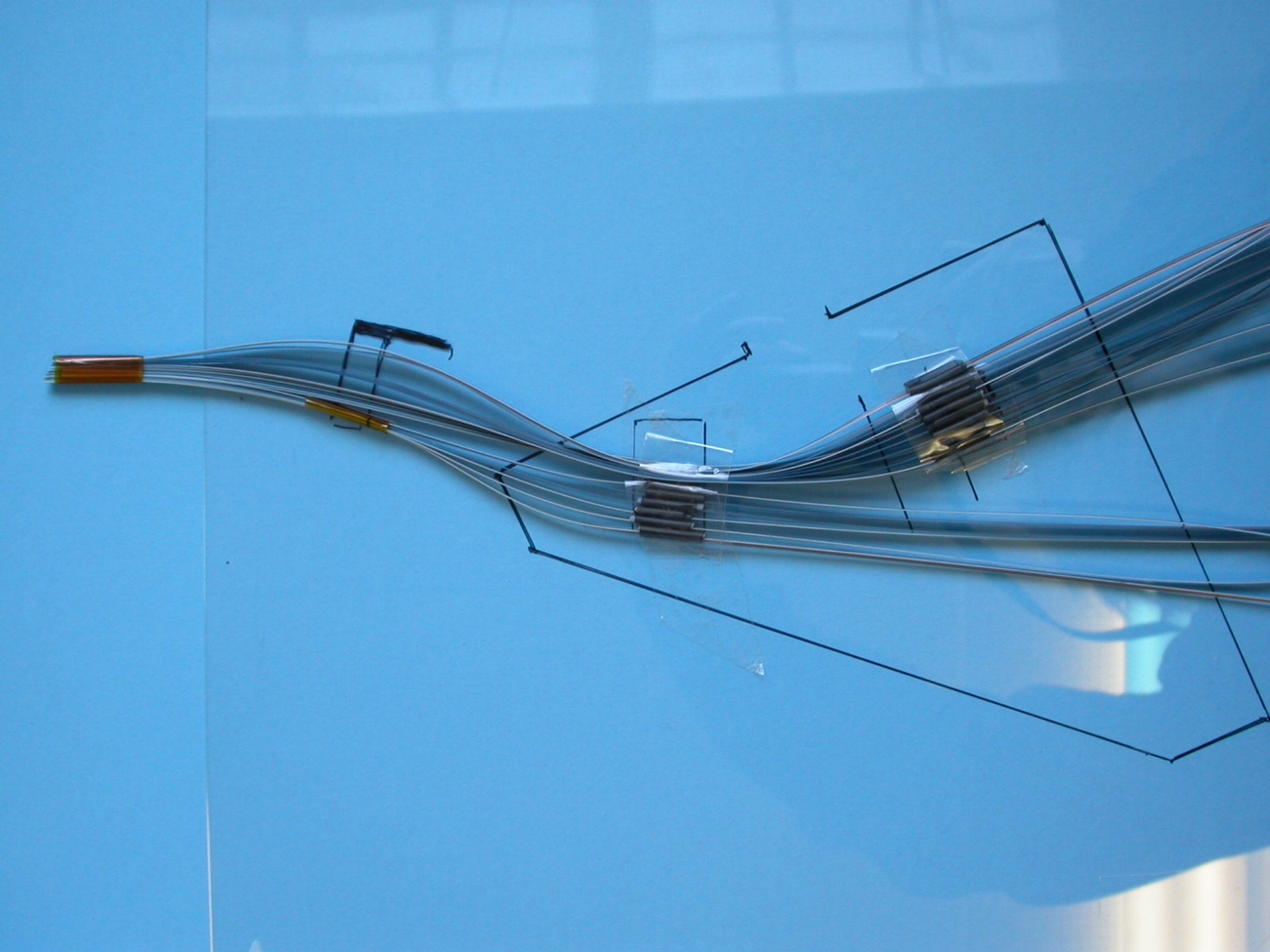
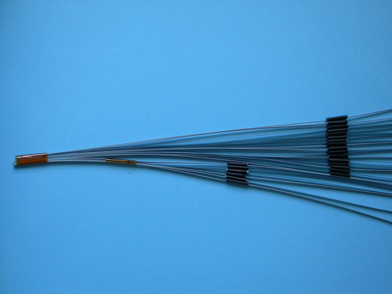
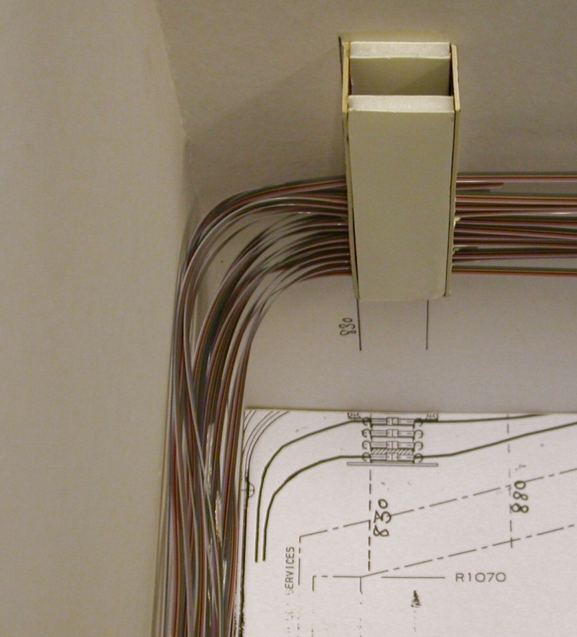
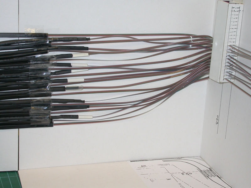
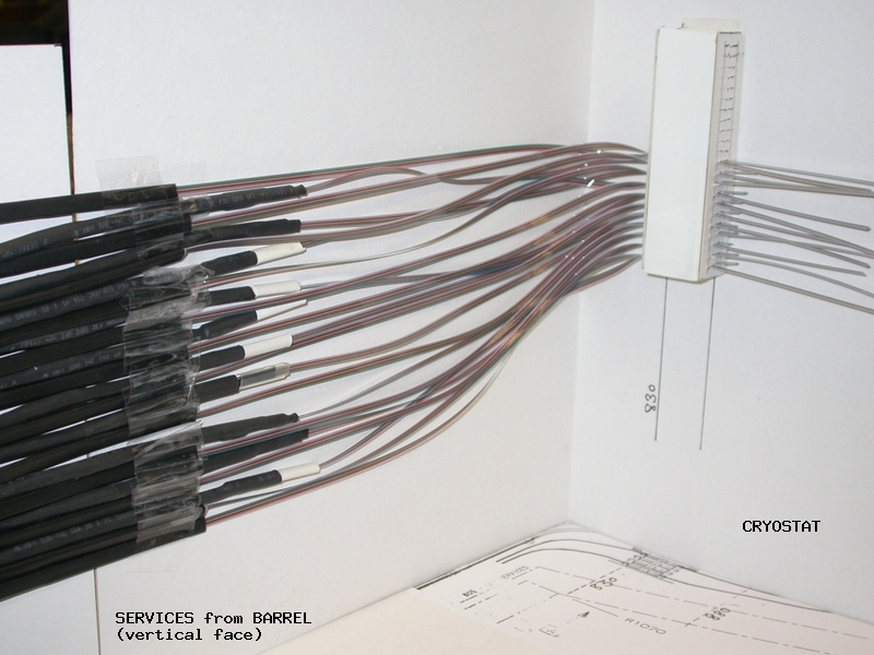
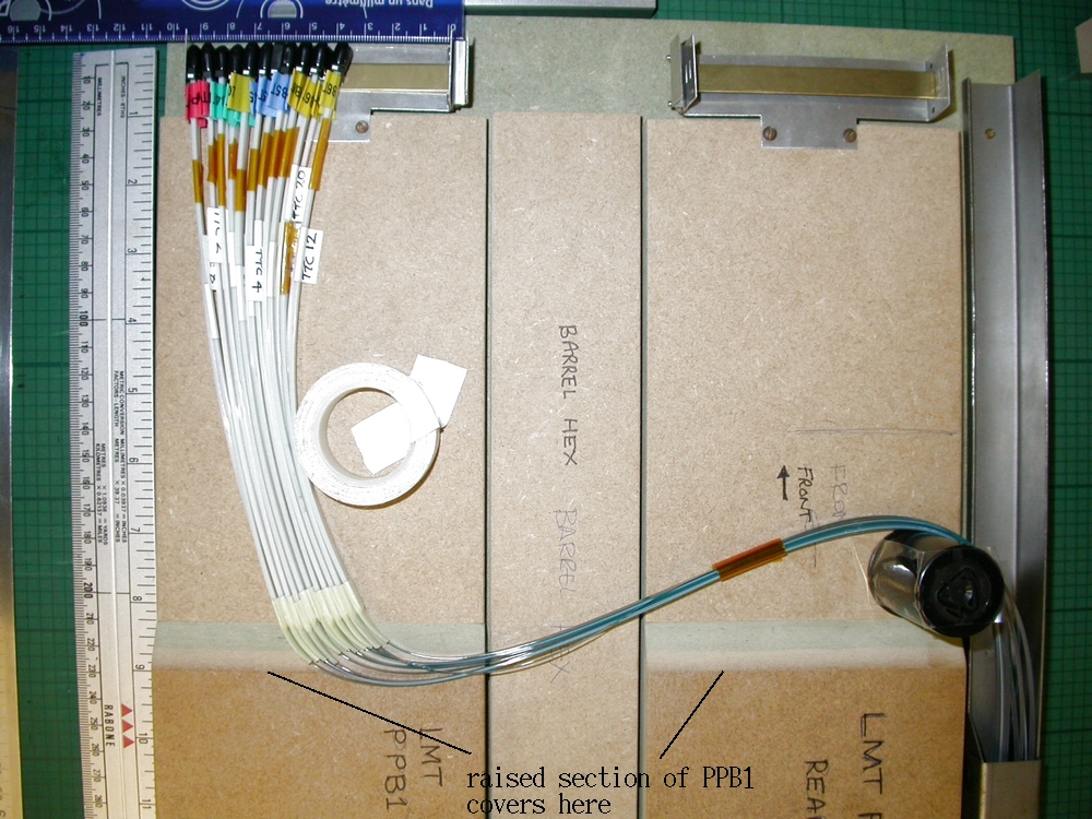
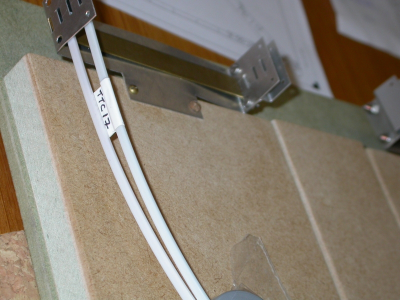
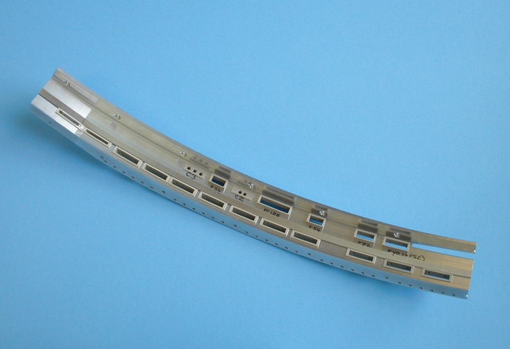
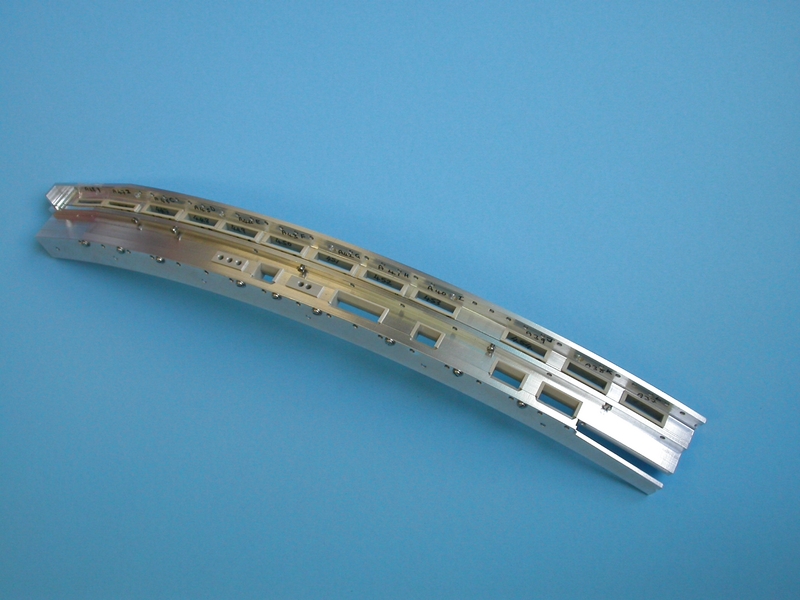
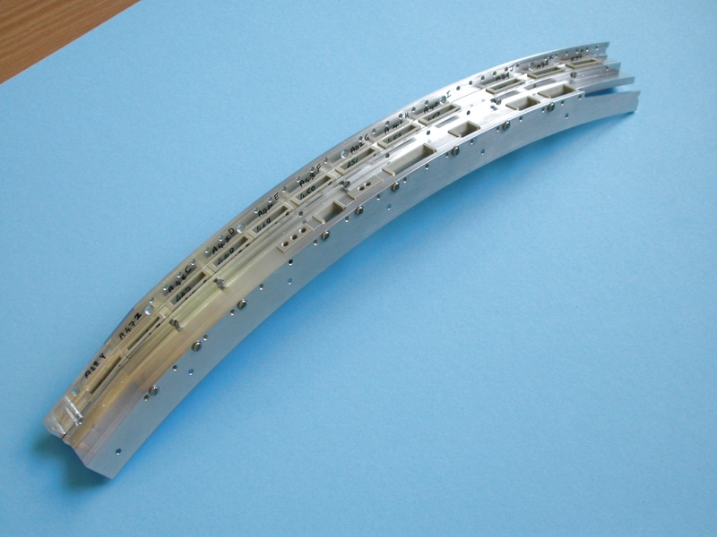
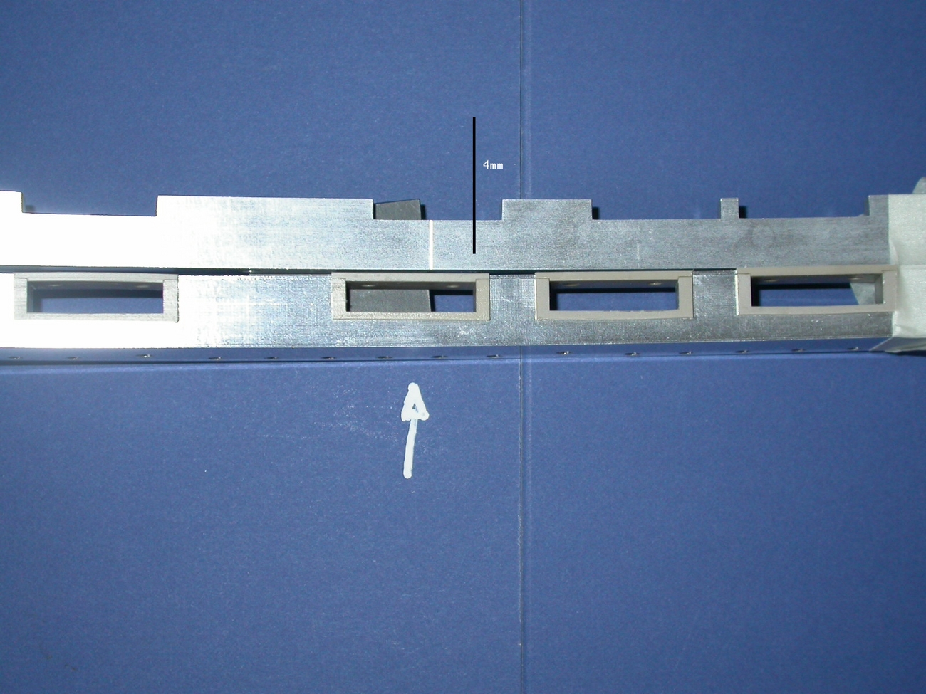
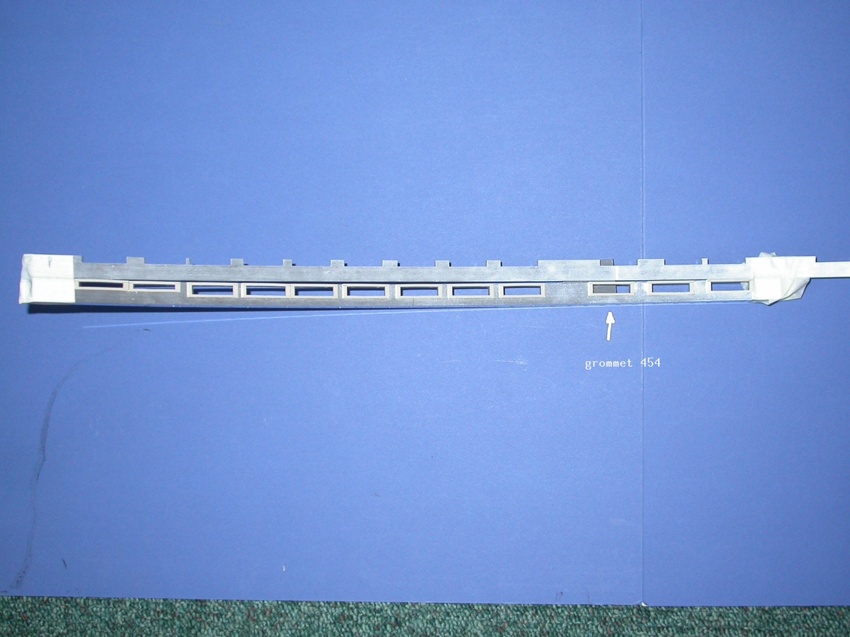
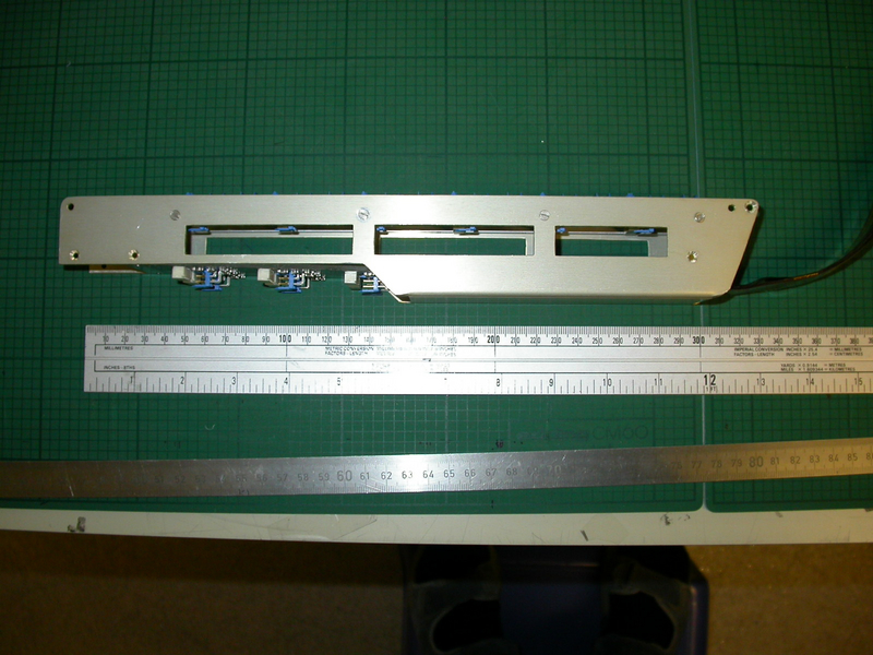
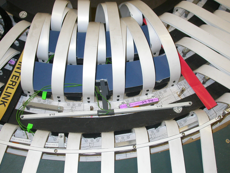
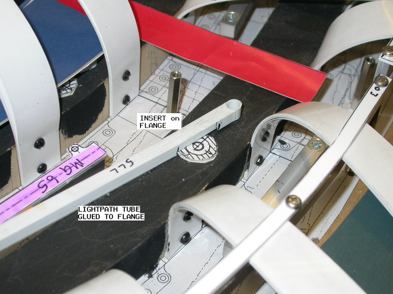
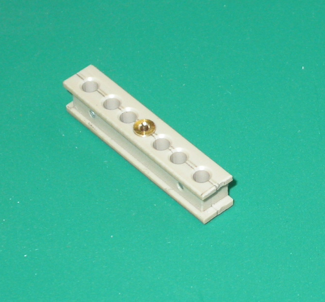
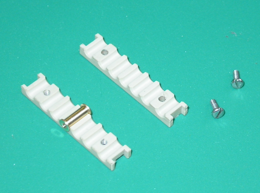
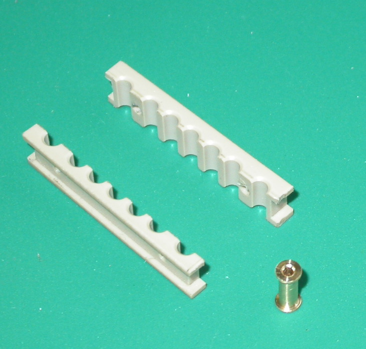
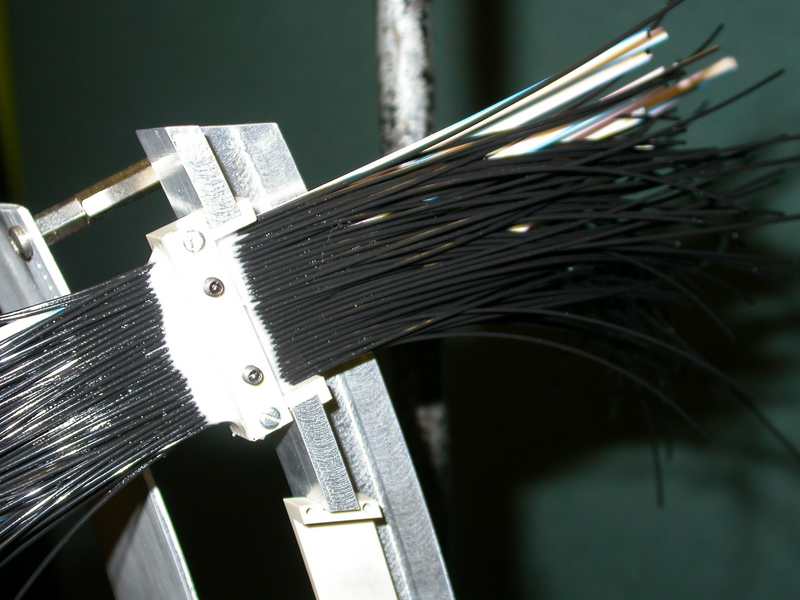
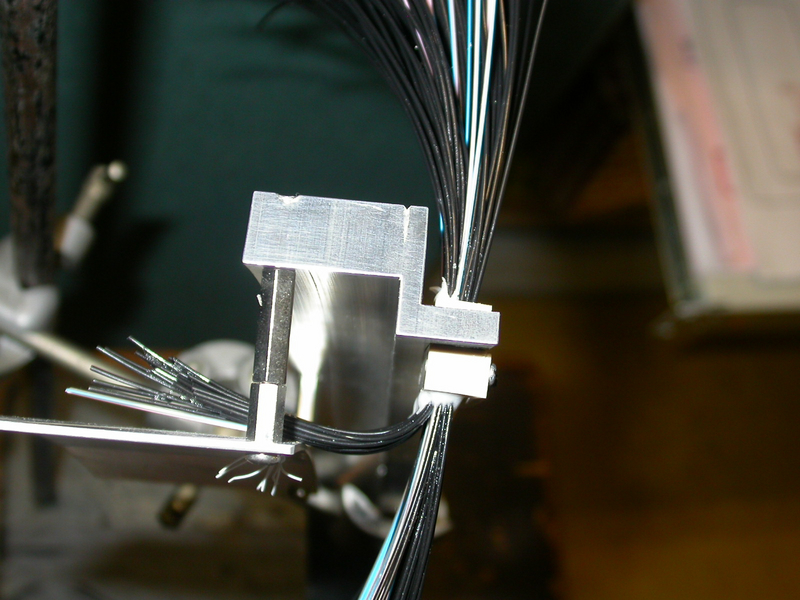
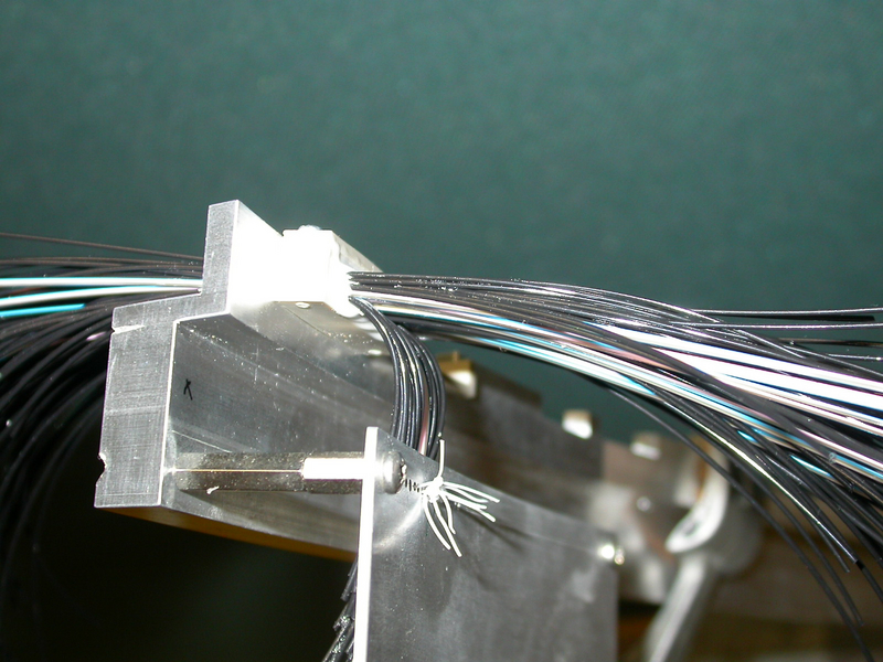
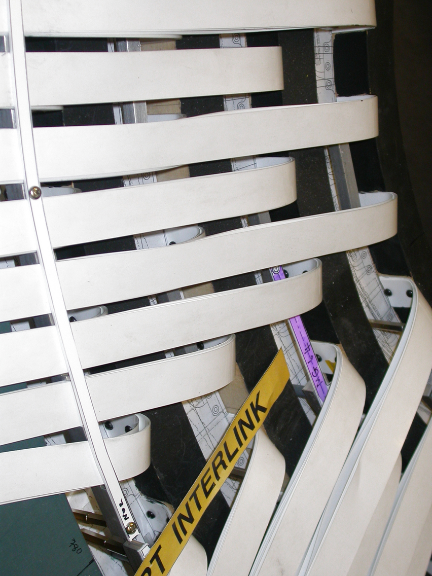
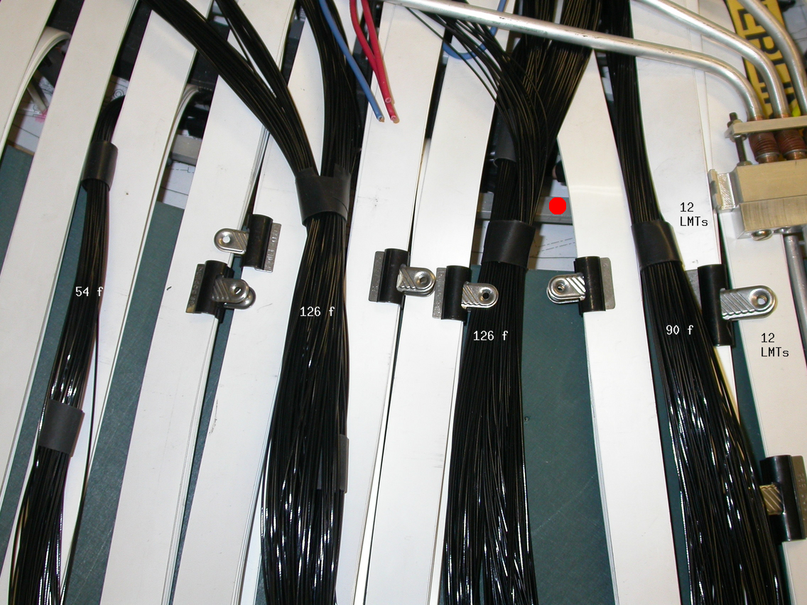
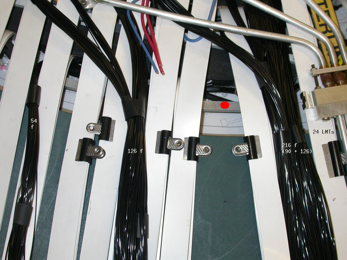
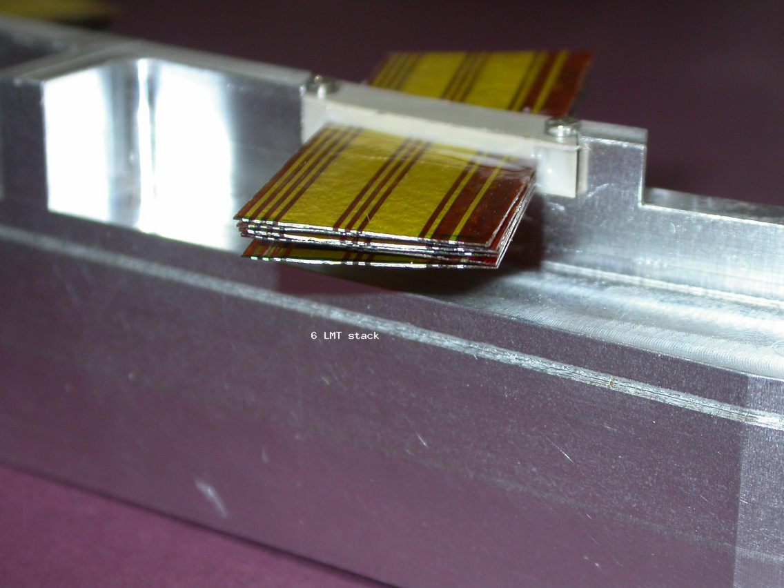
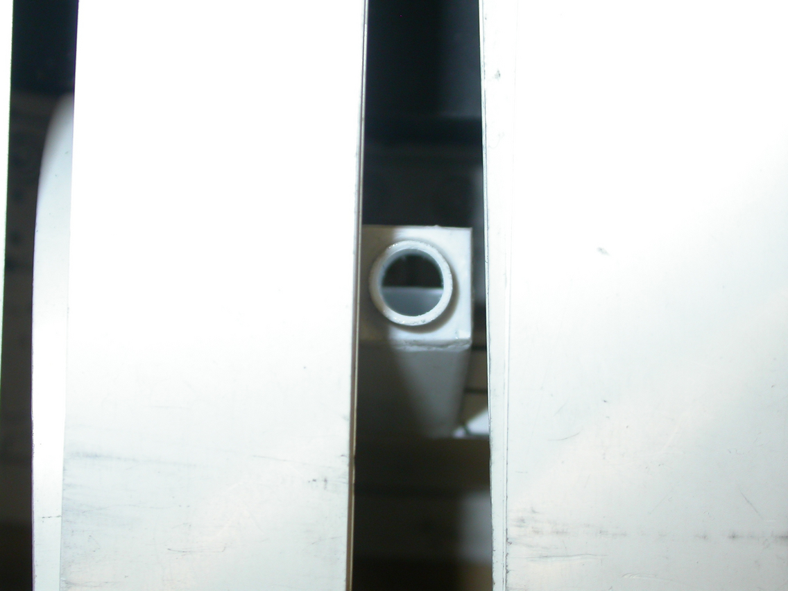
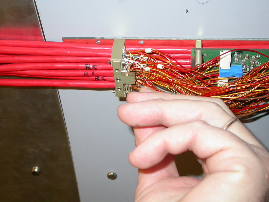
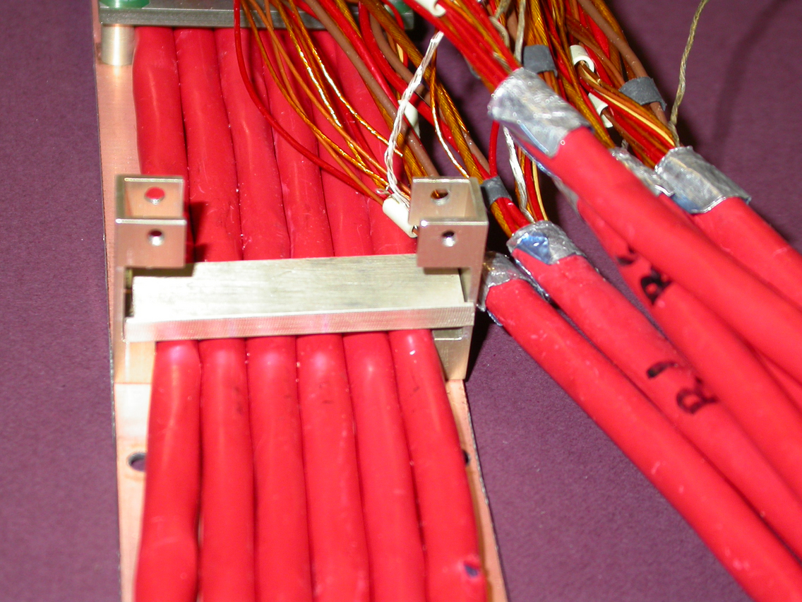
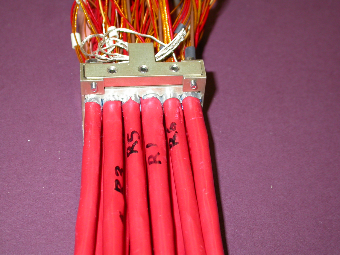
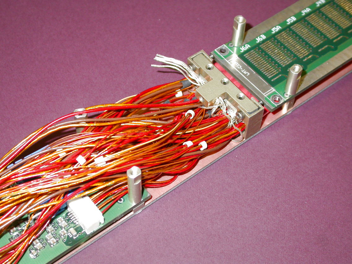
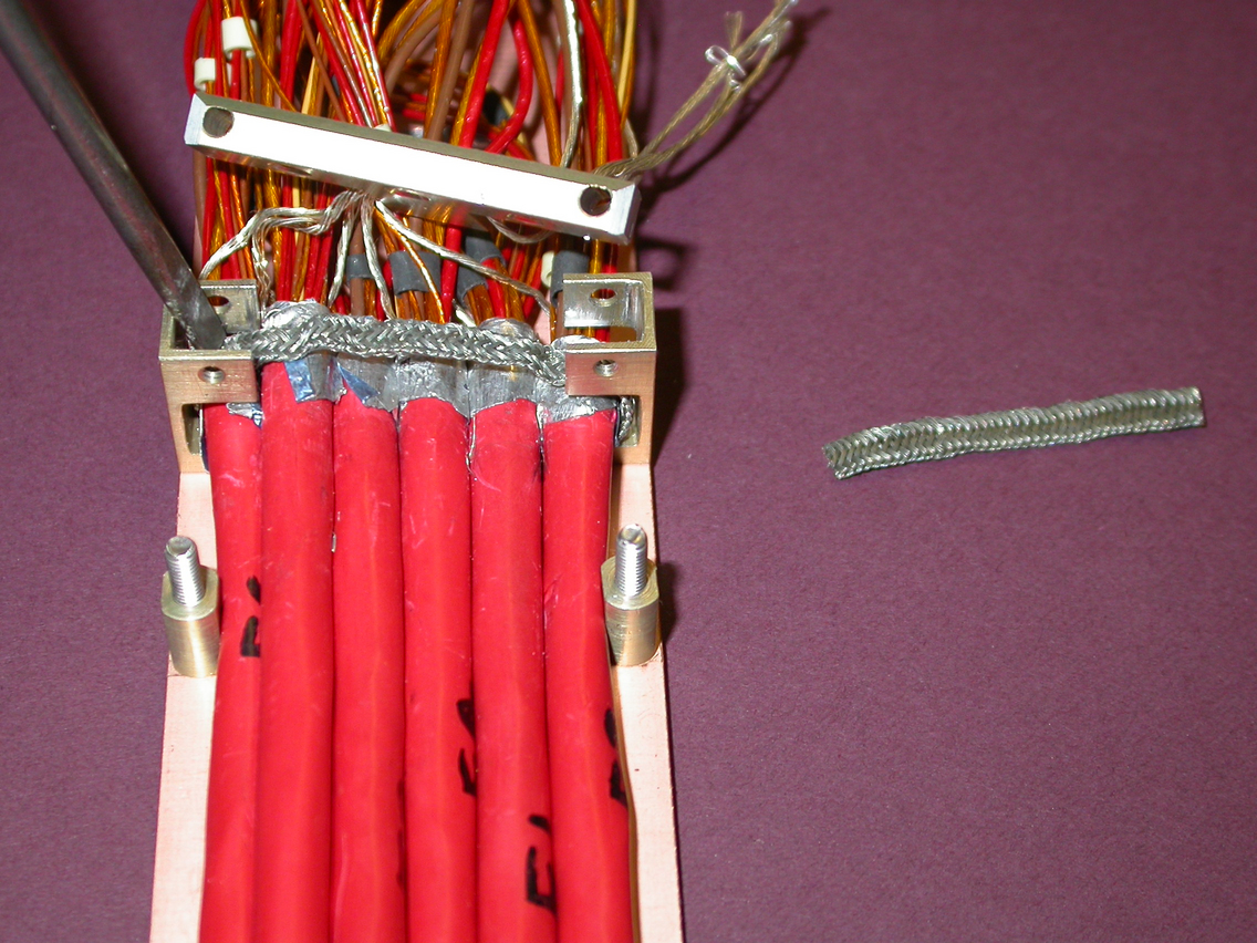
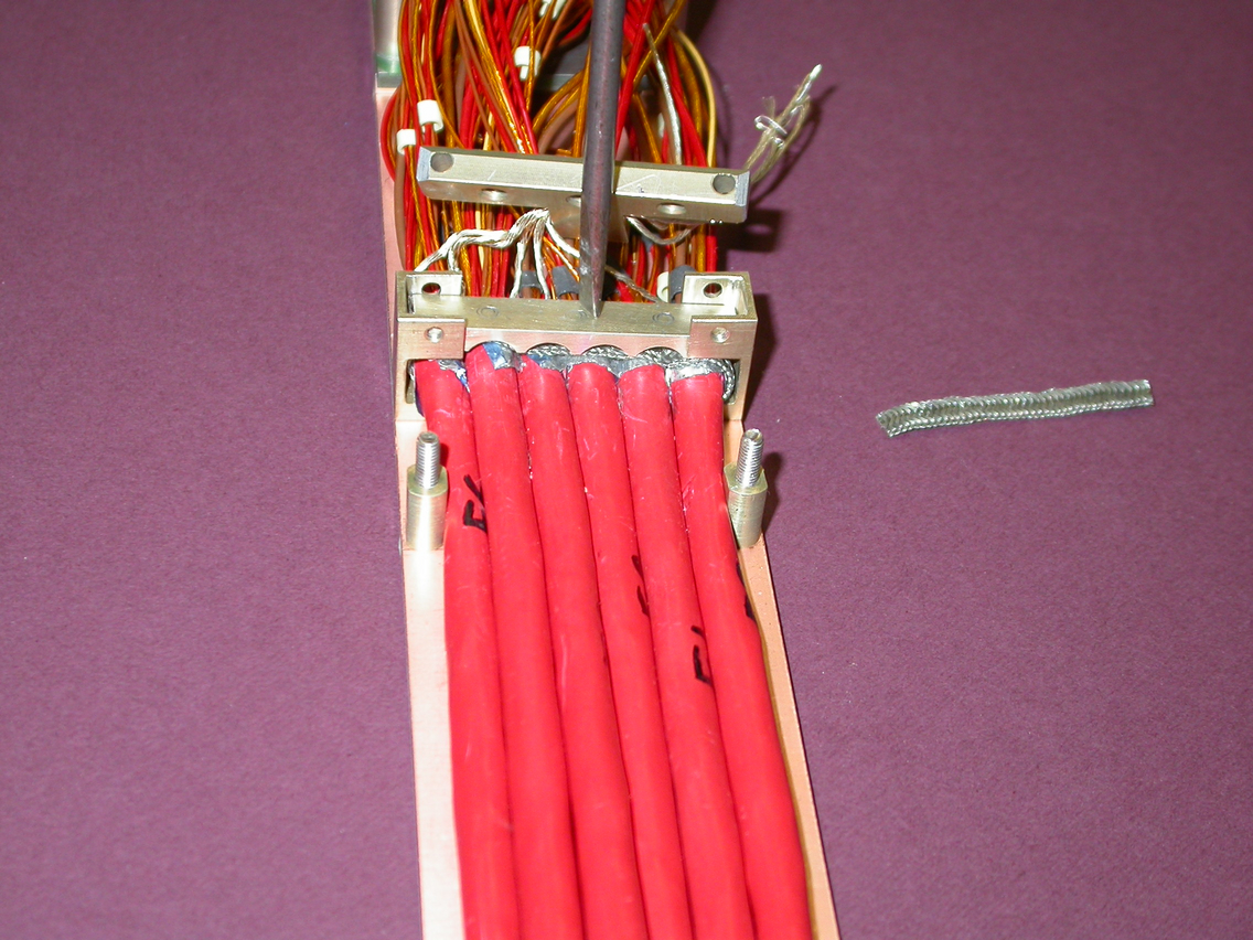
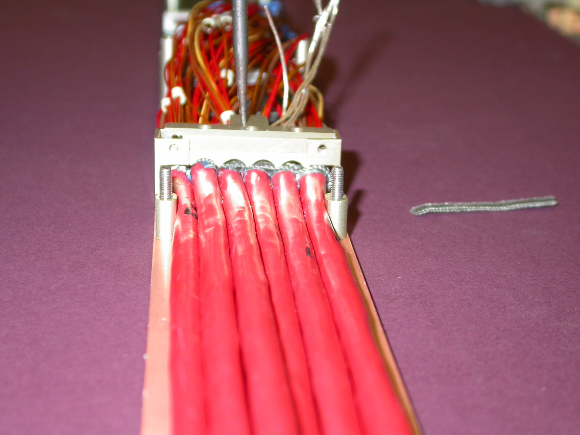
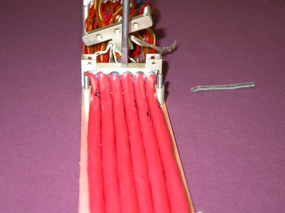
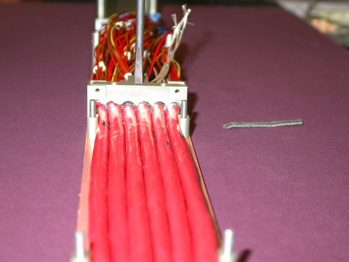
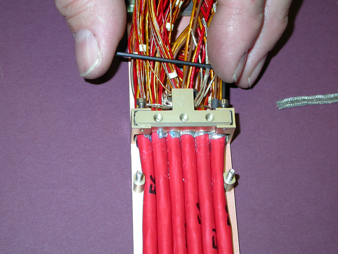
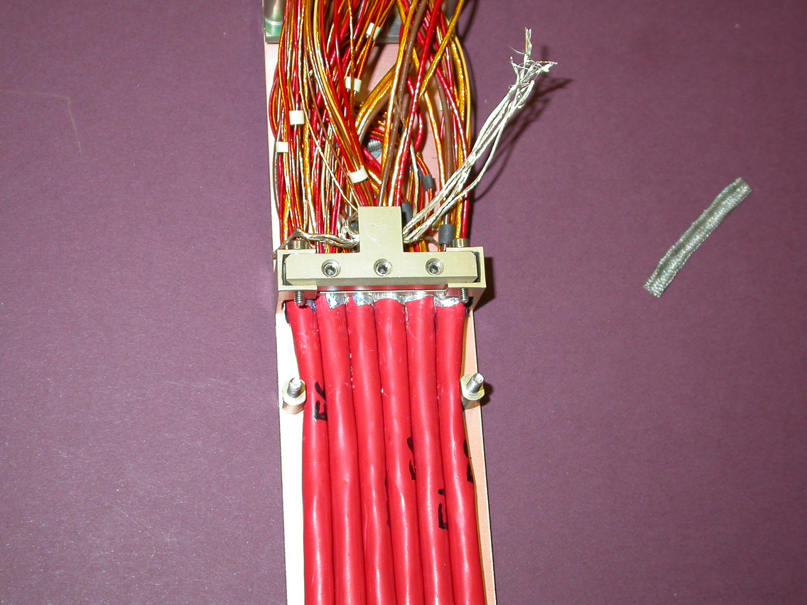
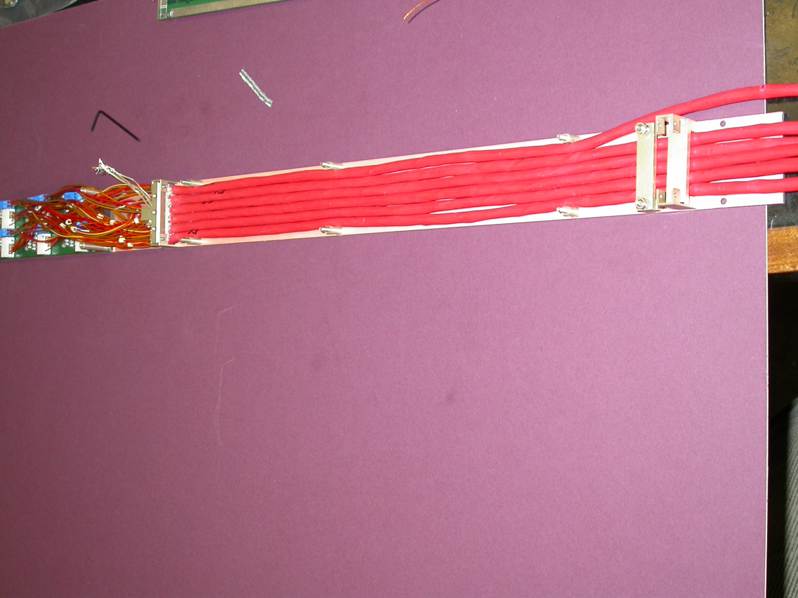
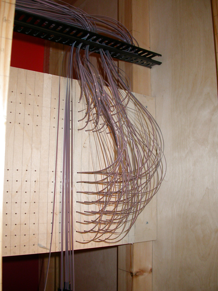
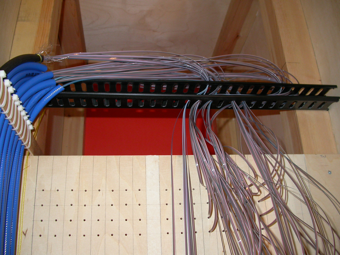
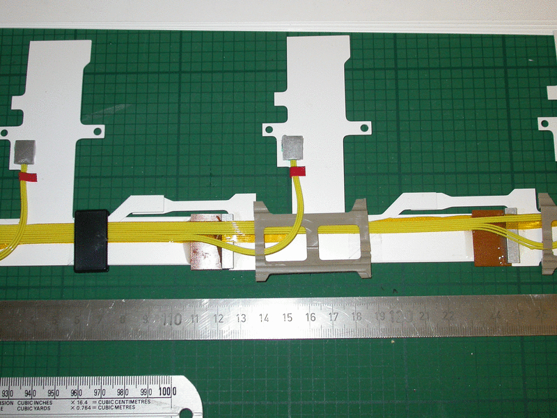
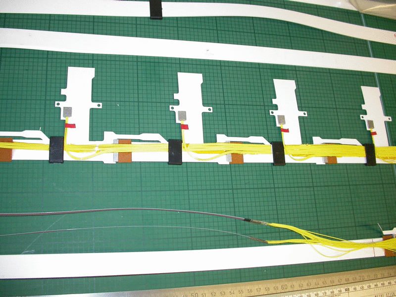
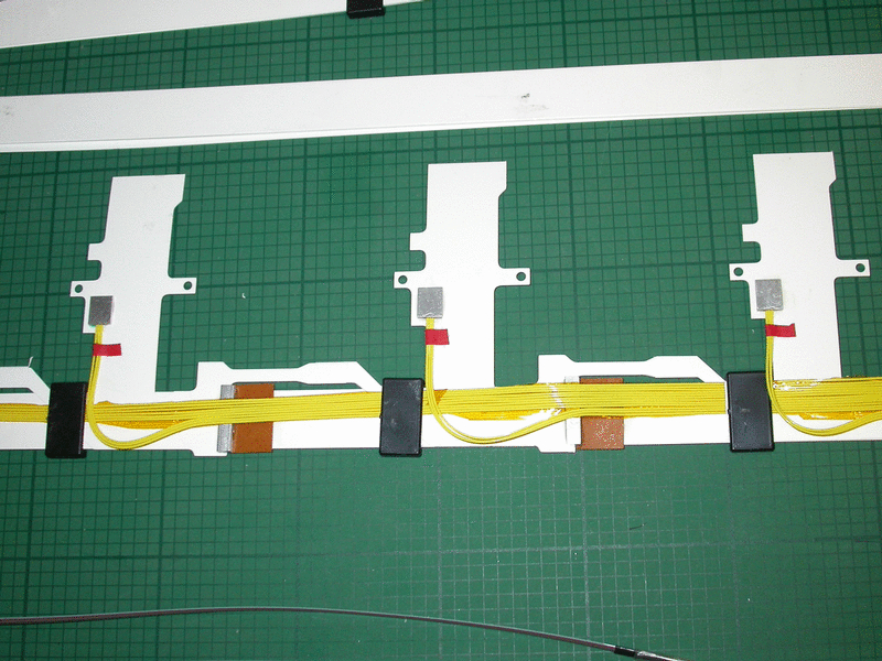
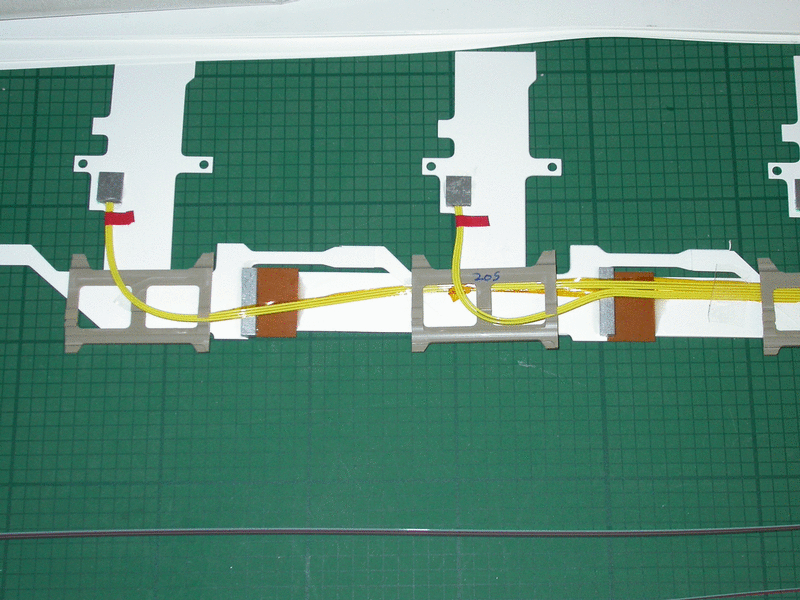
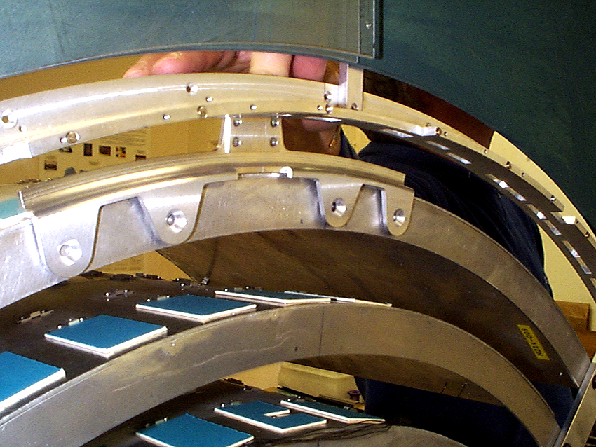
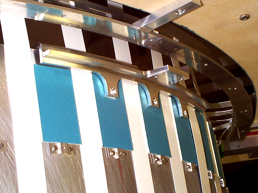
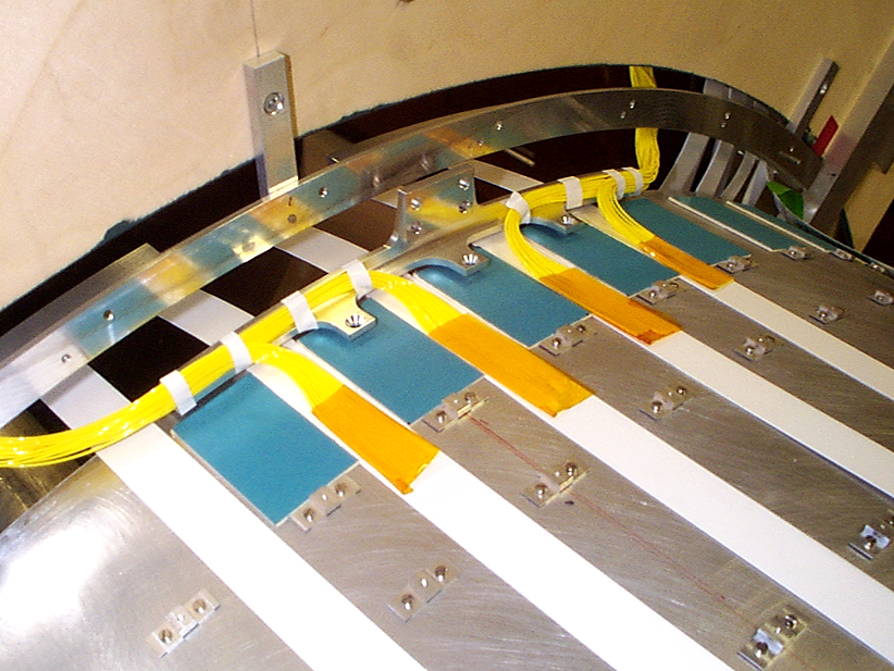
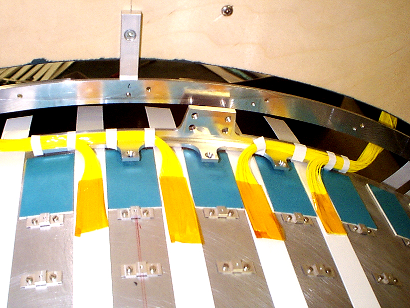
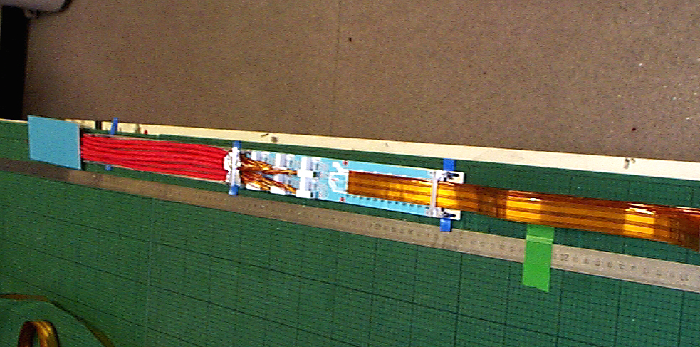
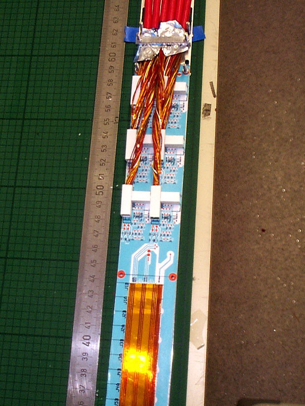
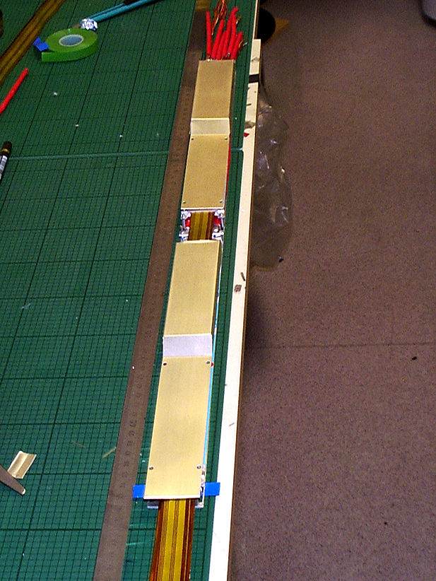
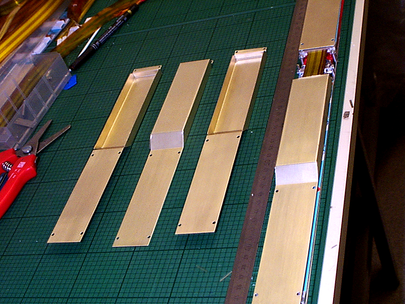
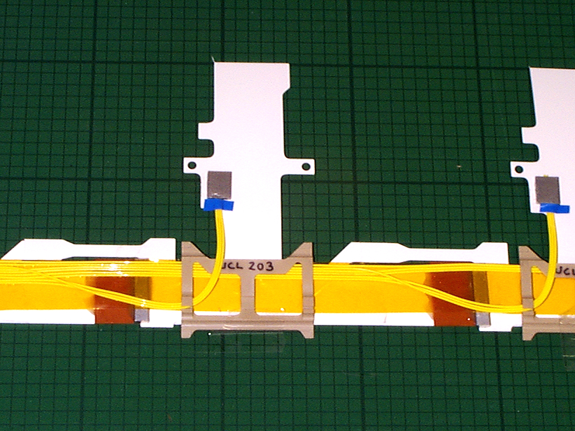
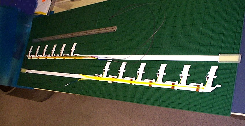
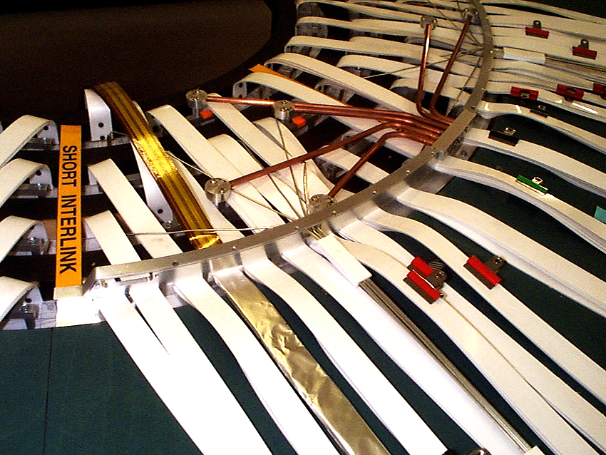
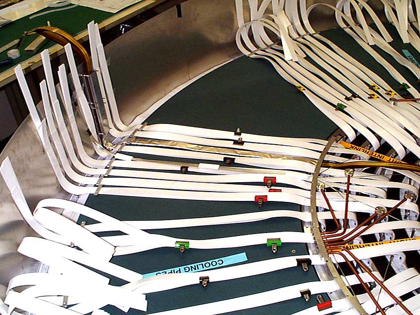
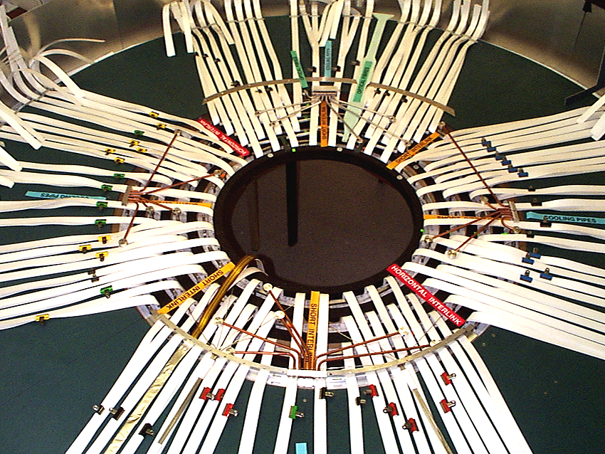
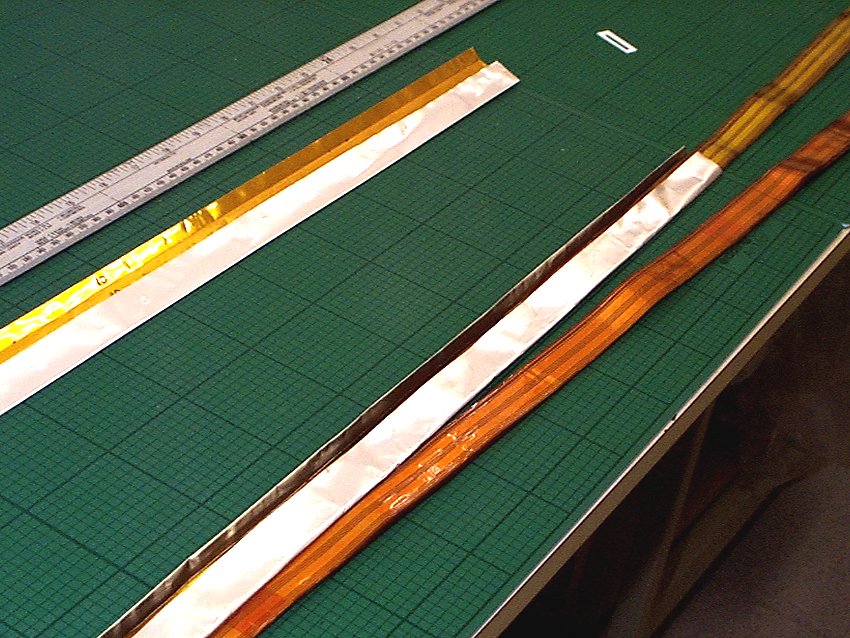
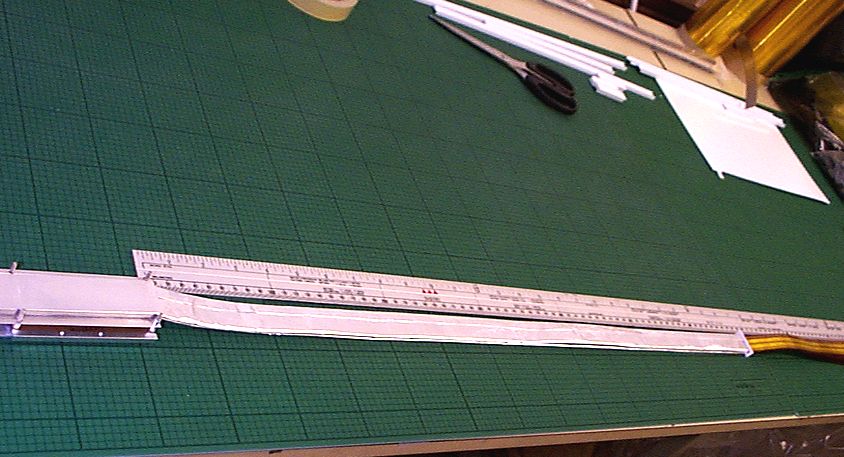
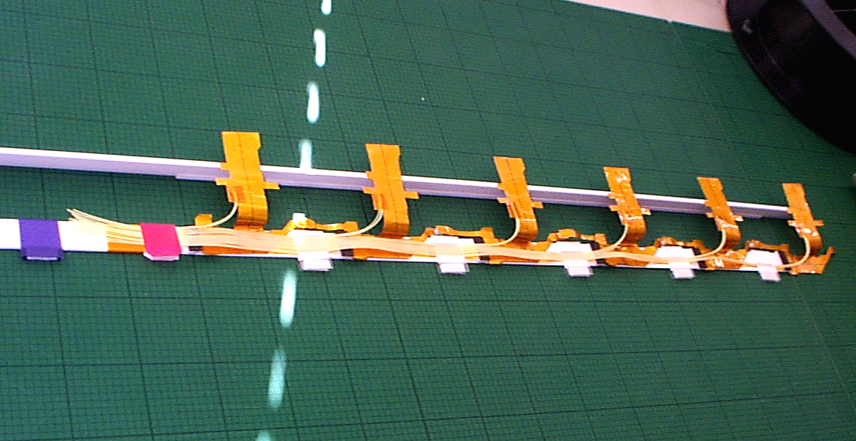
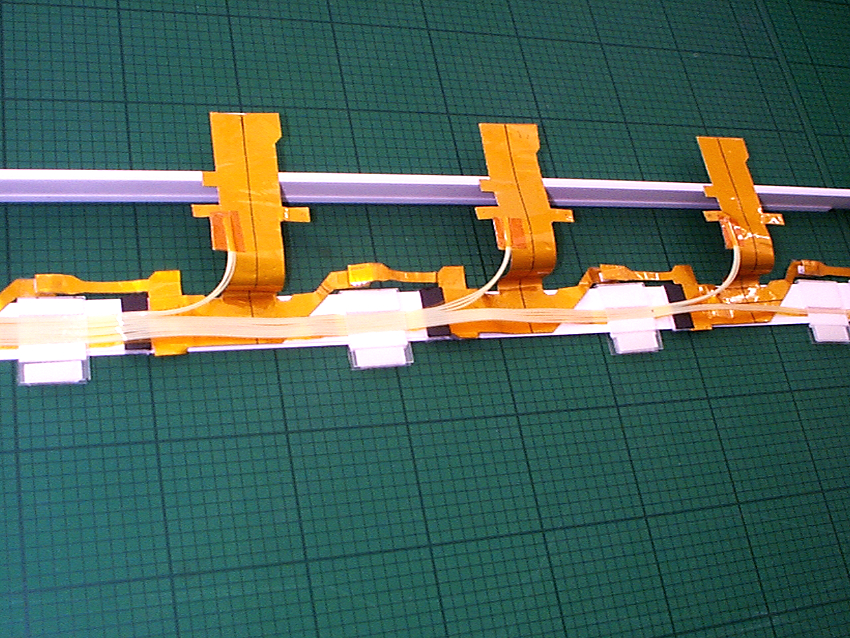
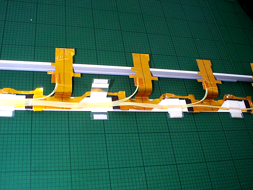
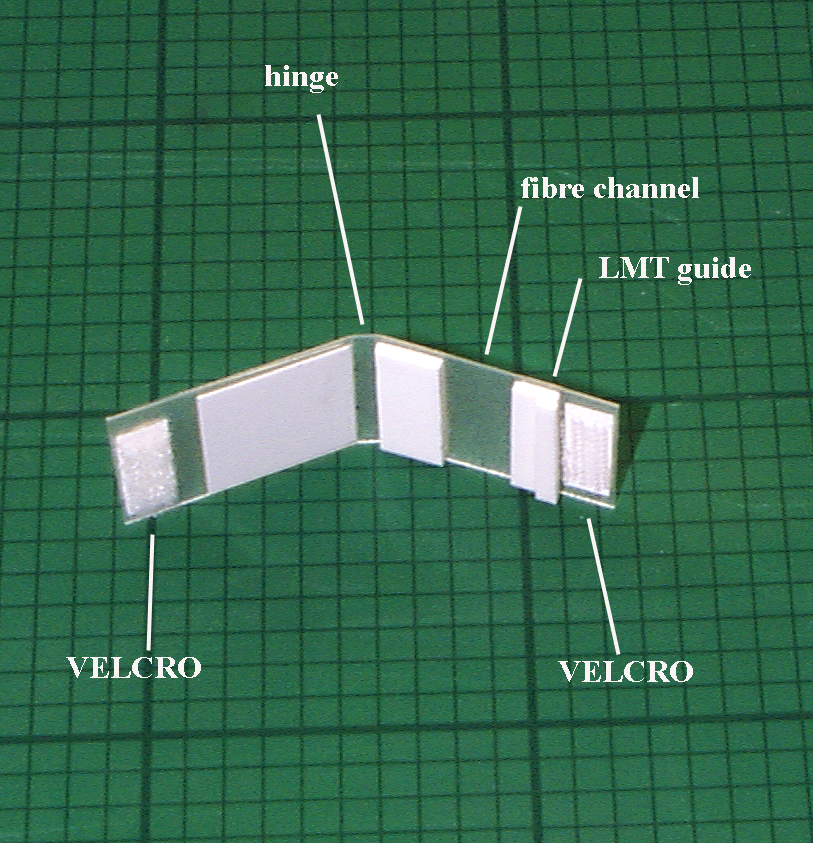
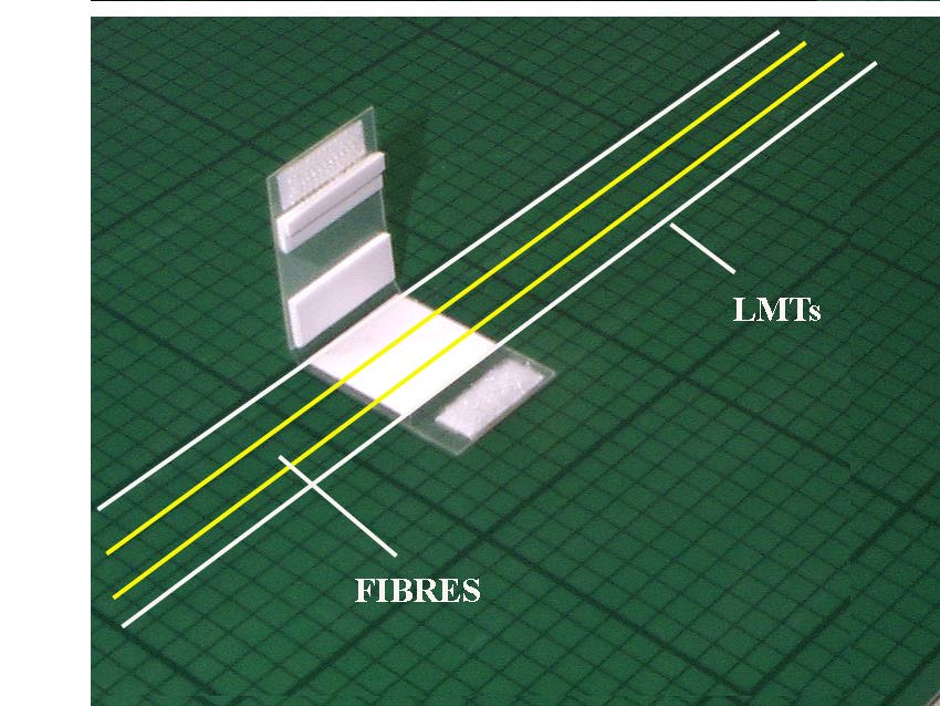
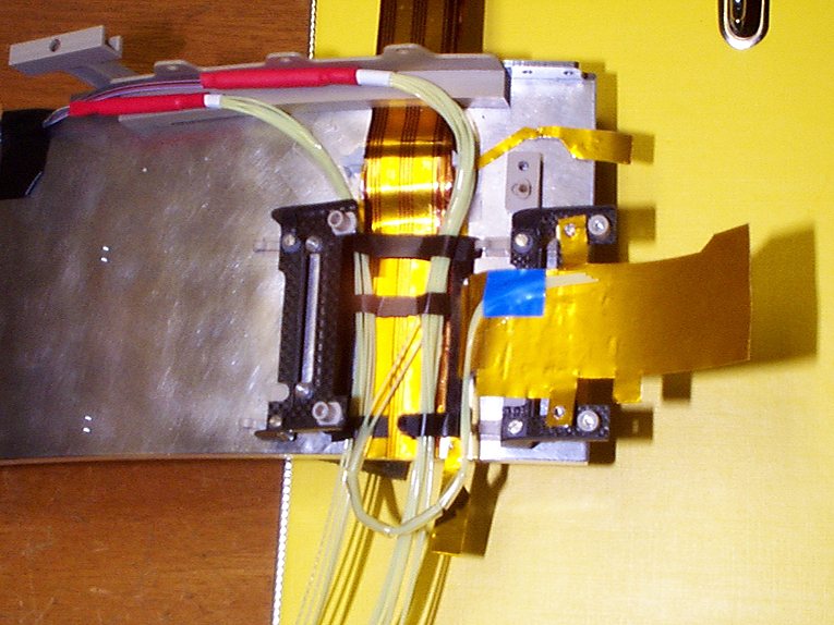
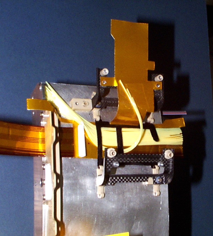
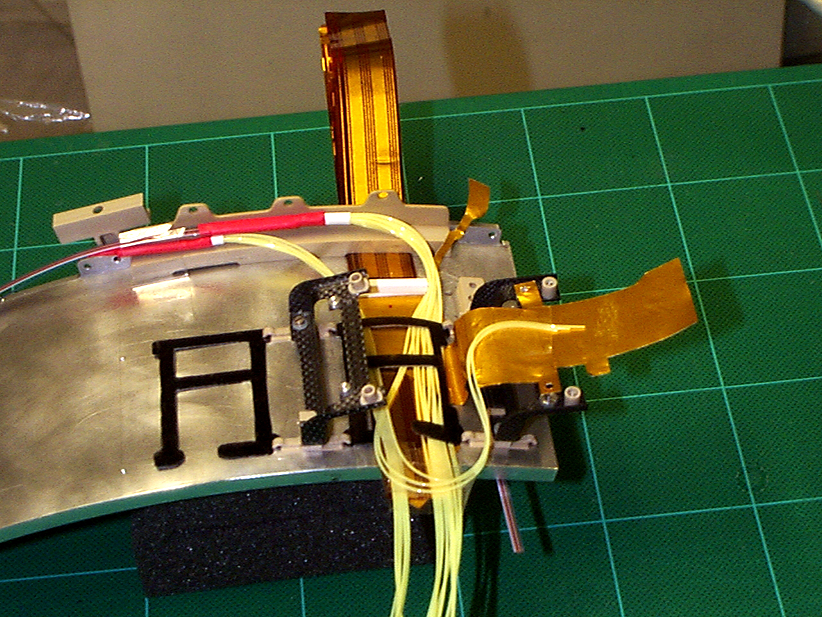
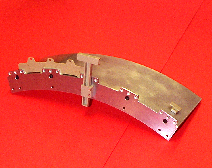
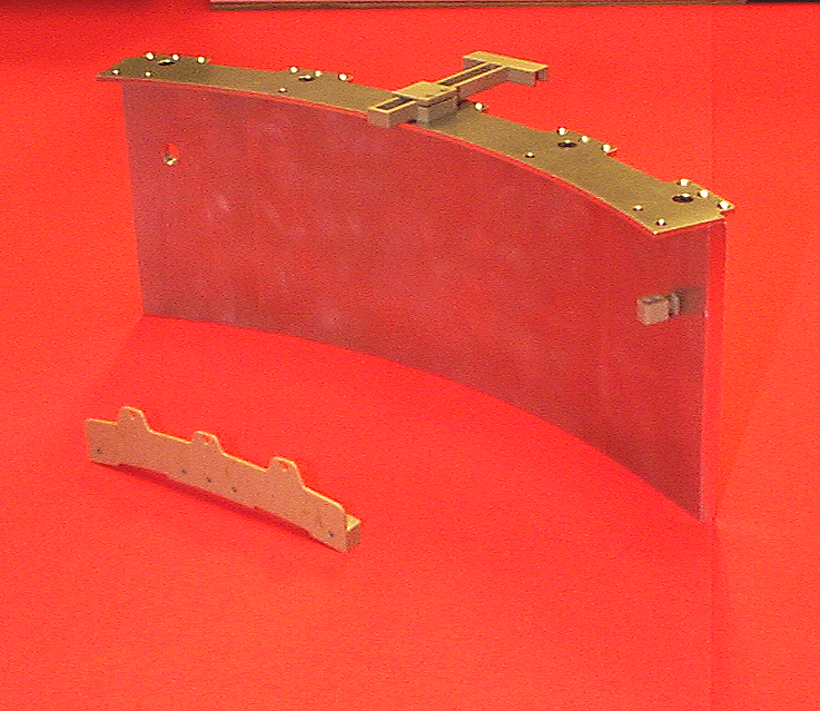
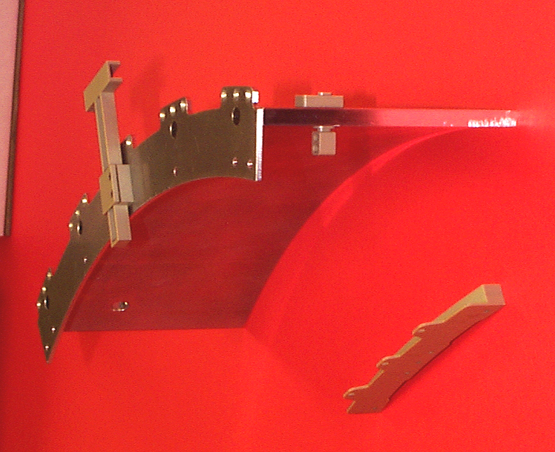
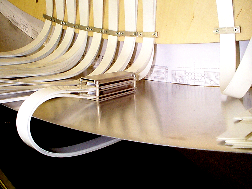
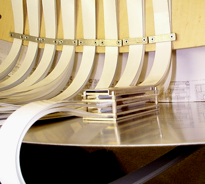
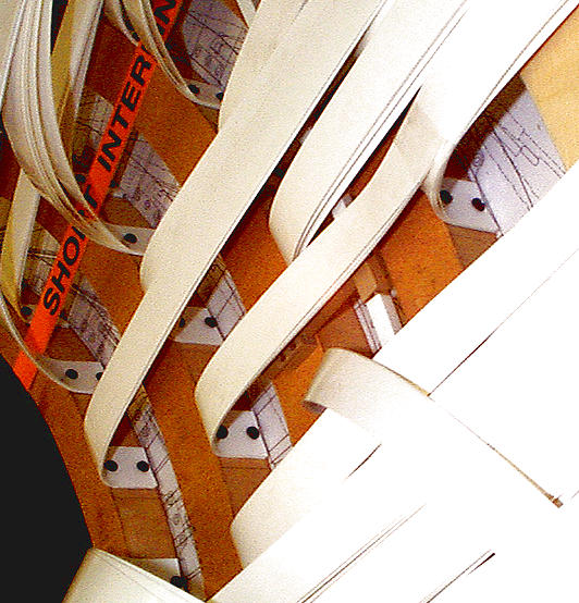
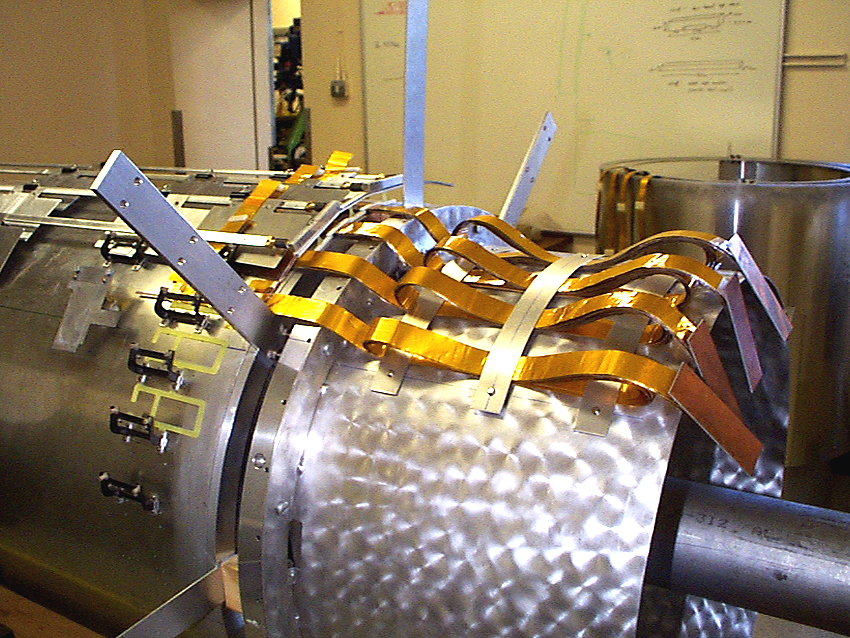
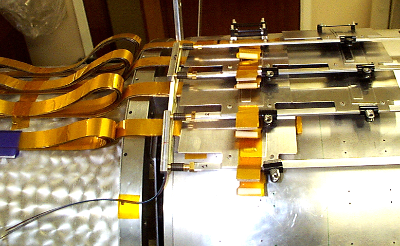
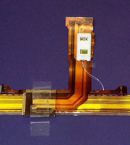
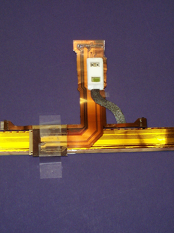
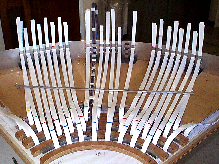
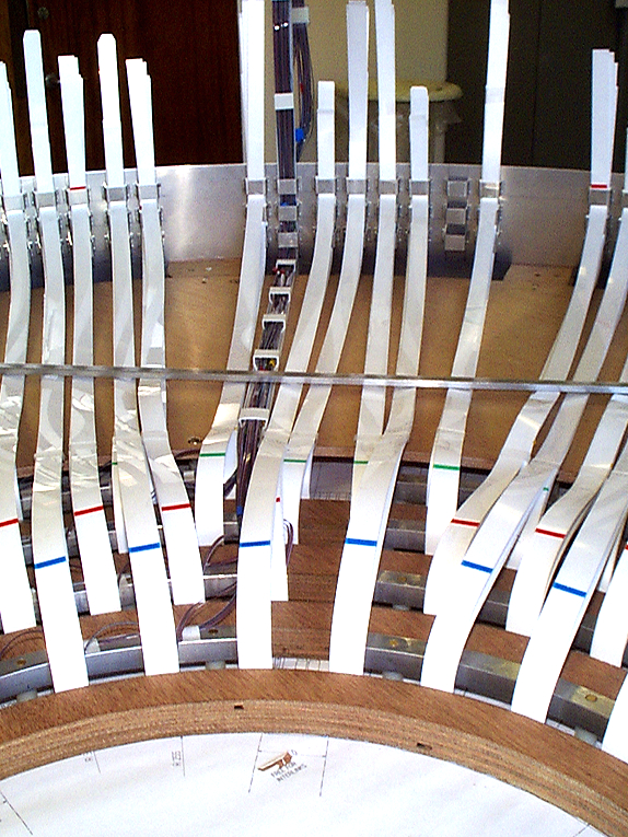
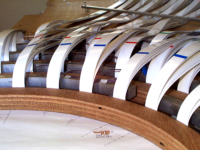
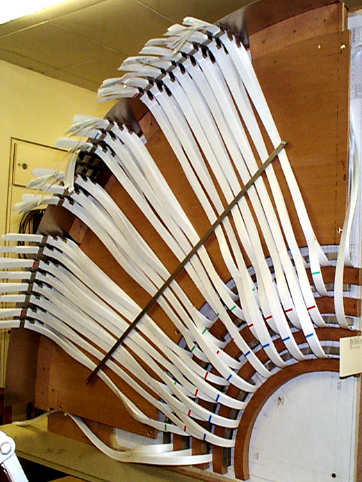
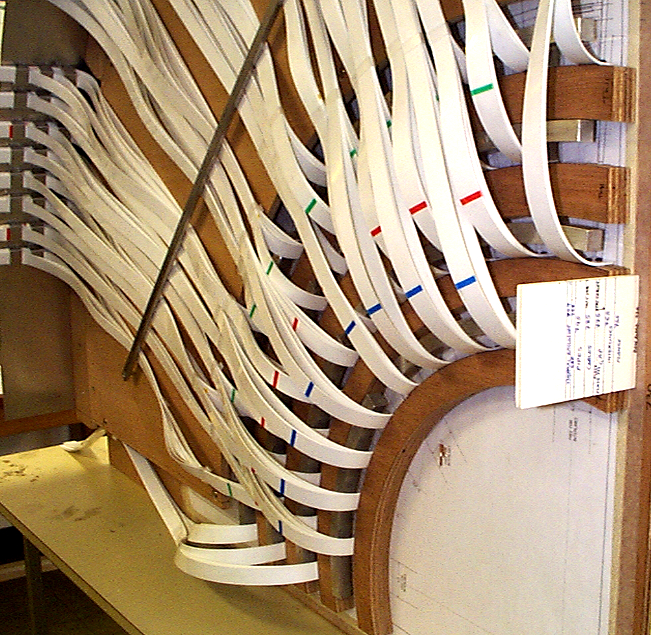
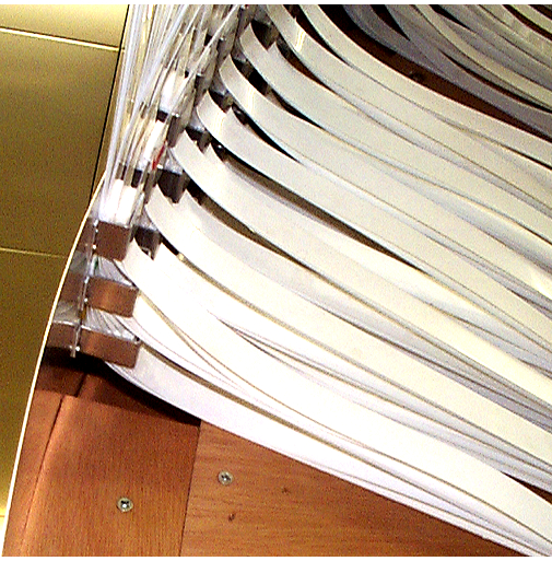
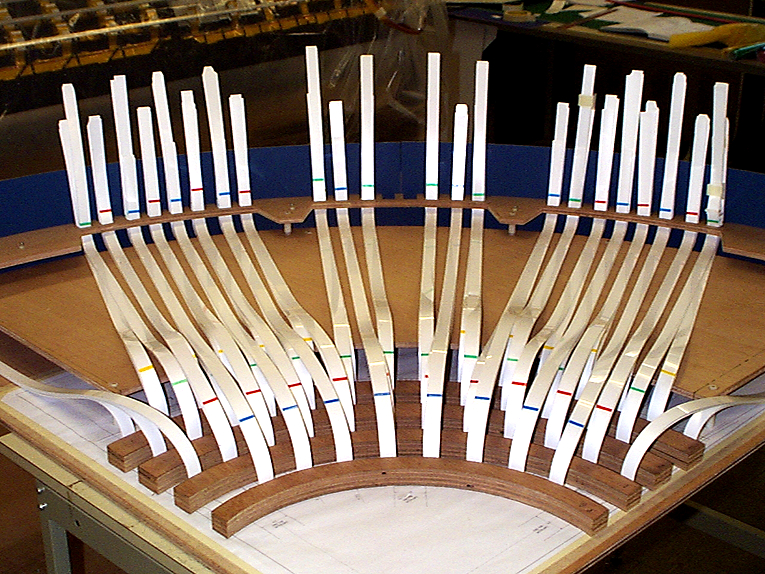
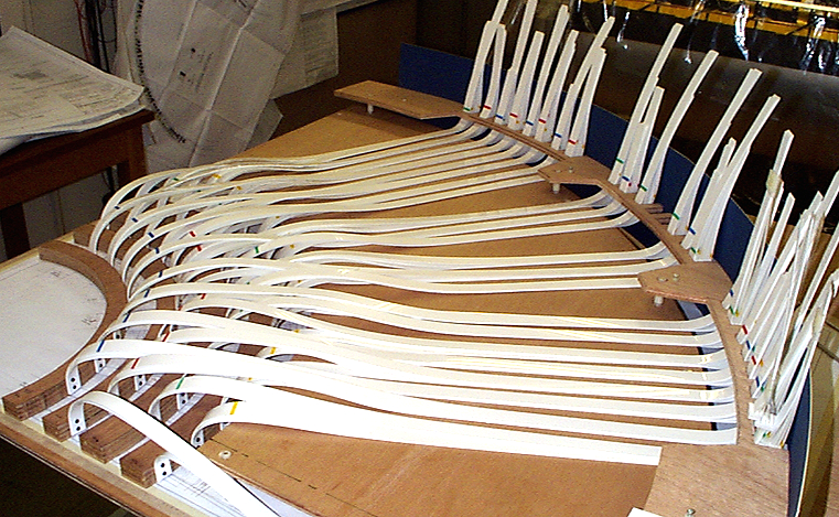
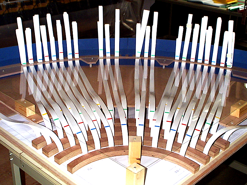
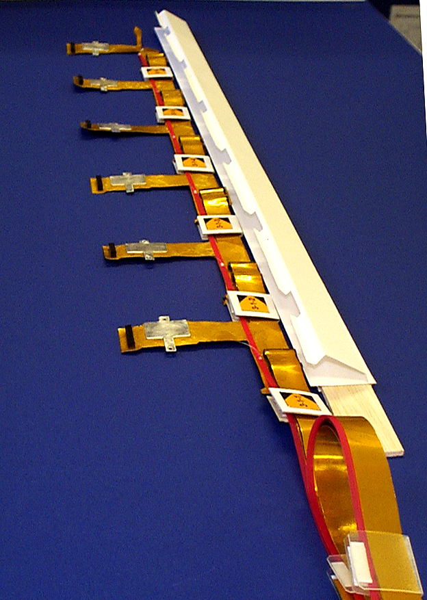
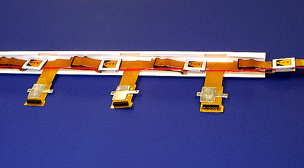
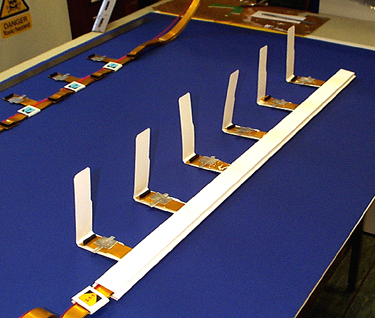
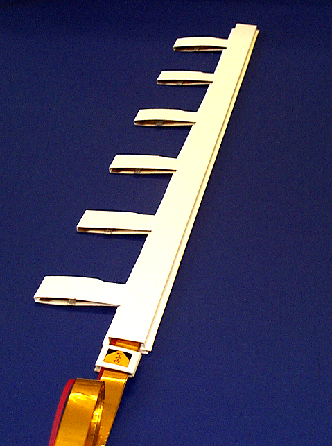
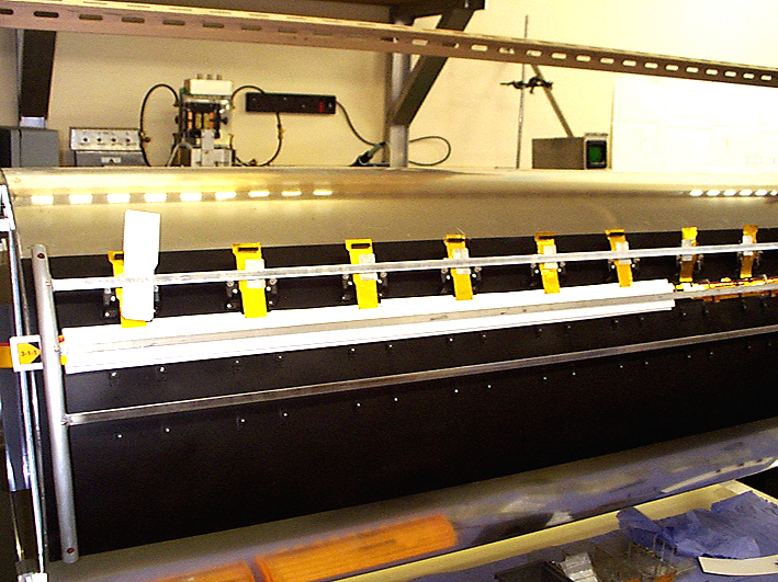
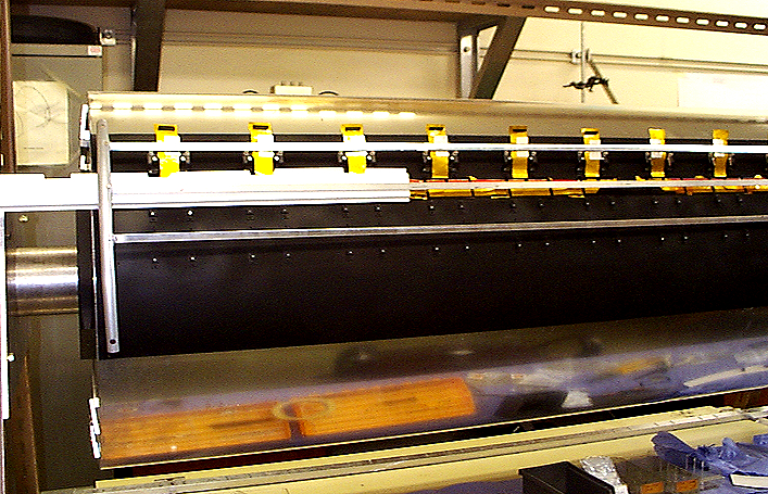
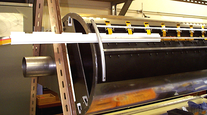
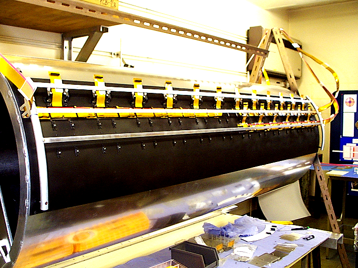
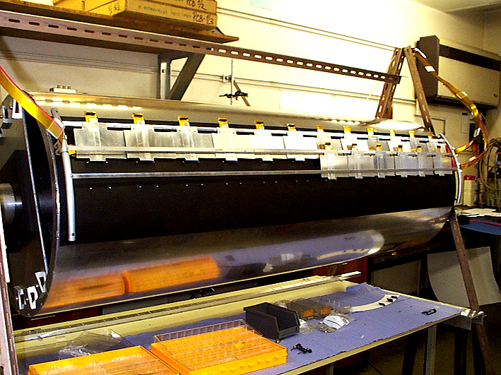
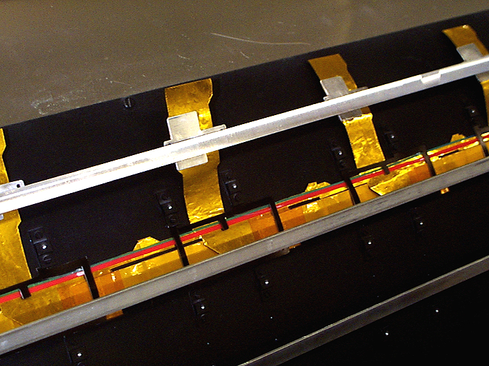
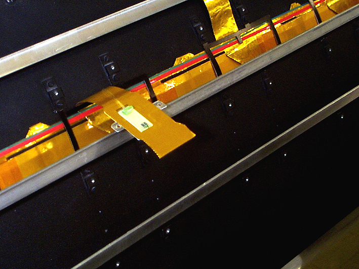
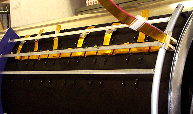
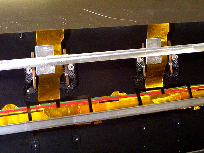
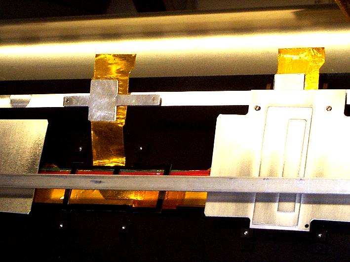
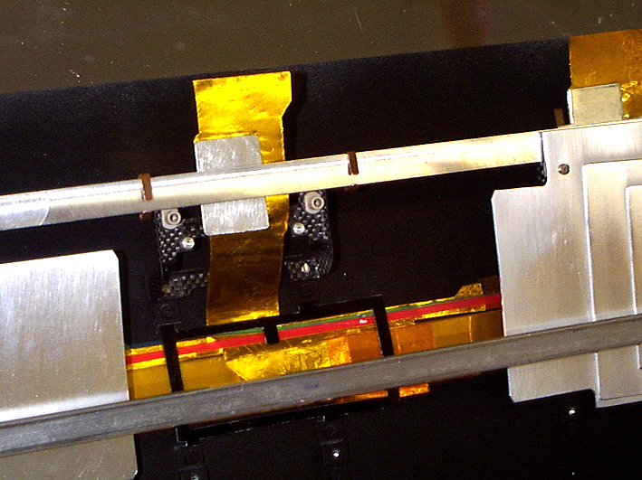
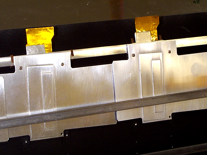
A new trial assembly of the LMT PPB1 boards on the support board has been made.
The assembly design and drawing has been made at RAL (drawing number TB-0049-401 Brian J. Smith).
Here are some photos of details of the PPB1 LMT assembly using production low mass tapes and real type II cables.
01/10/2003
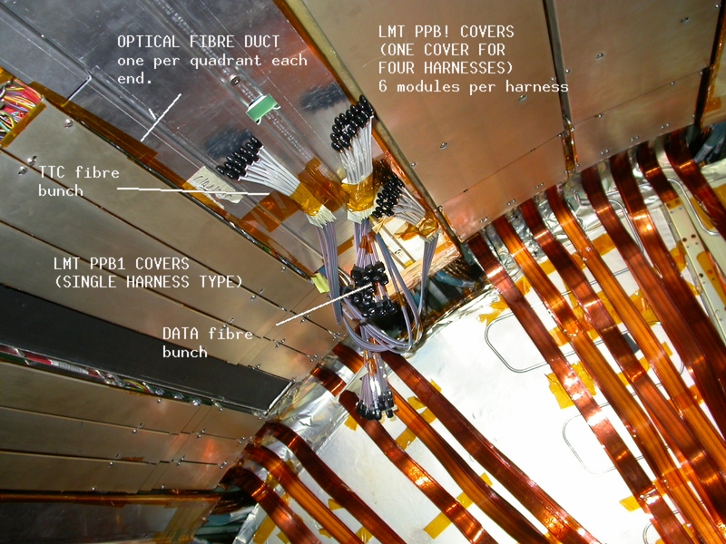
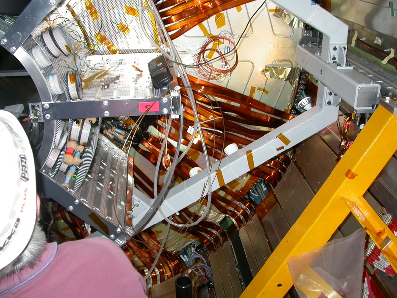
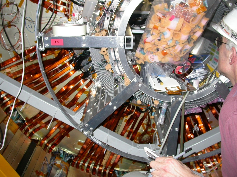
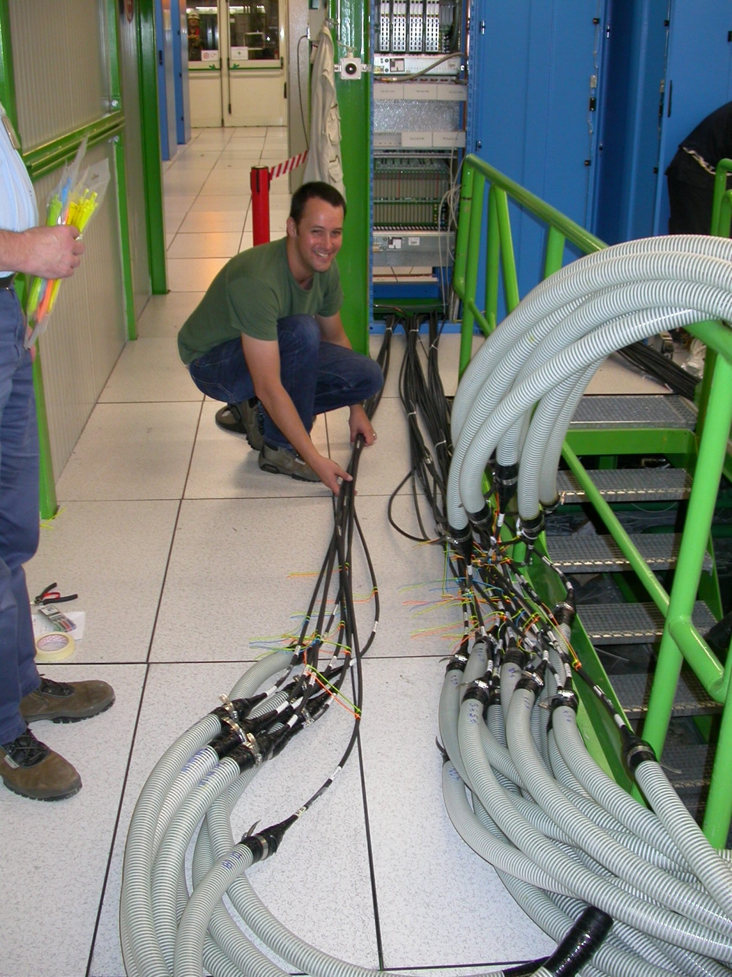
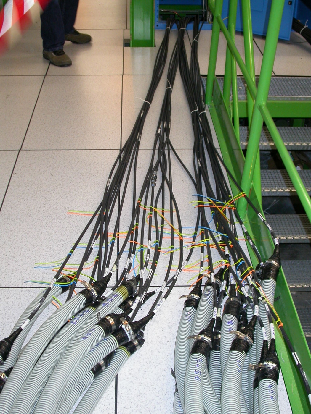
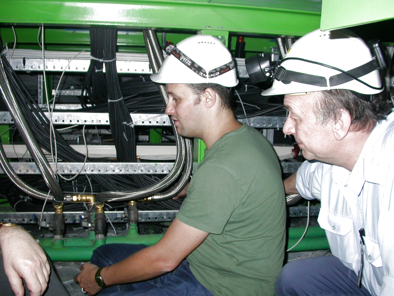
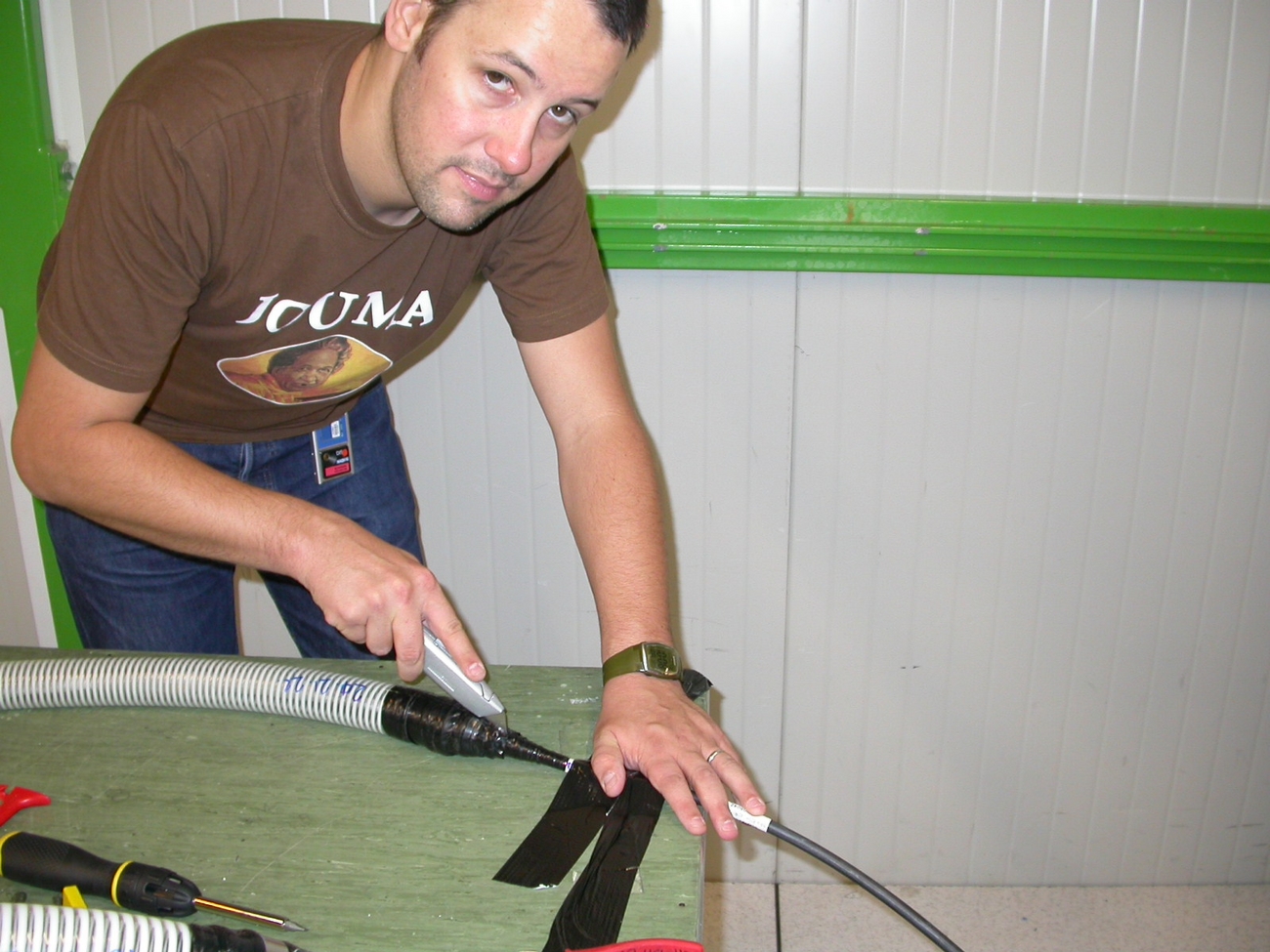
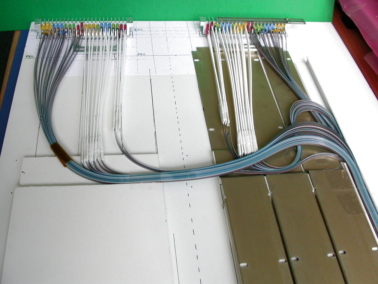
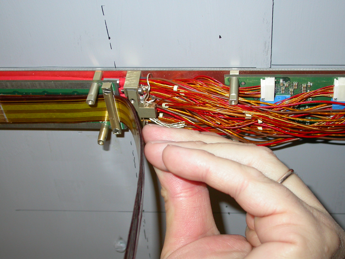
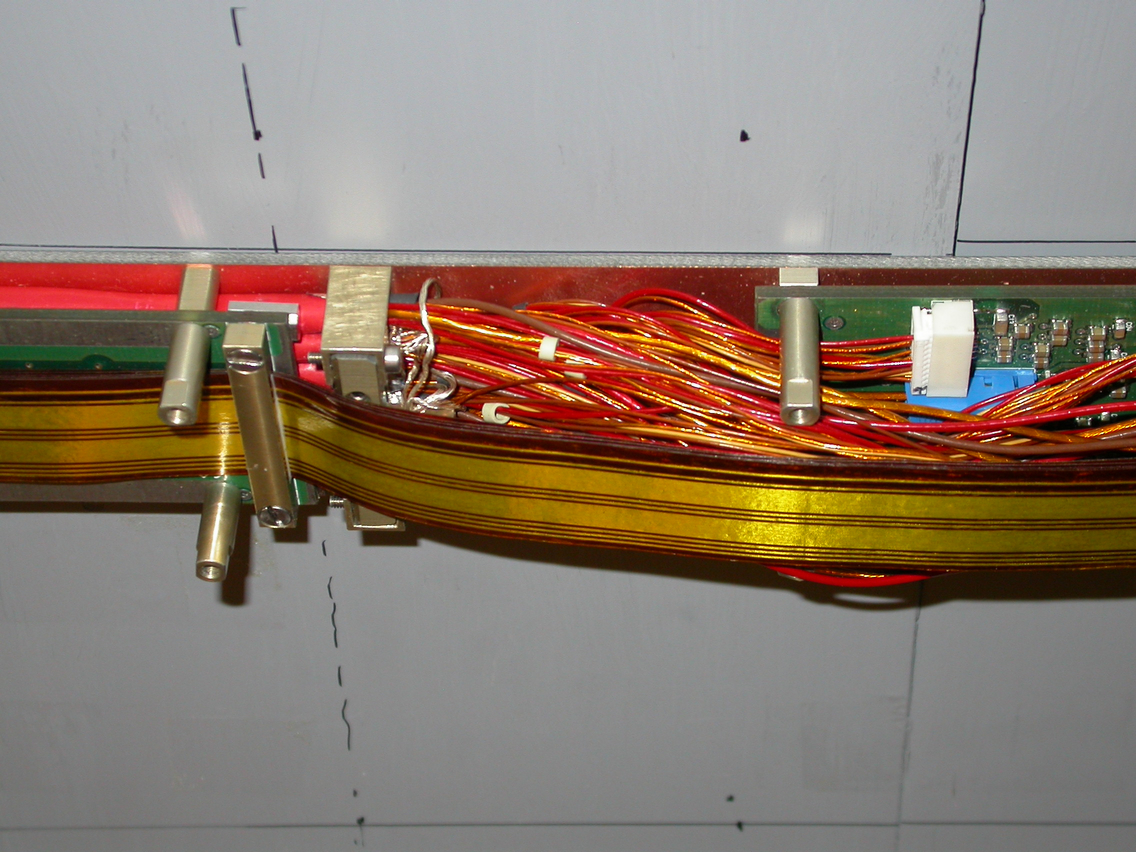
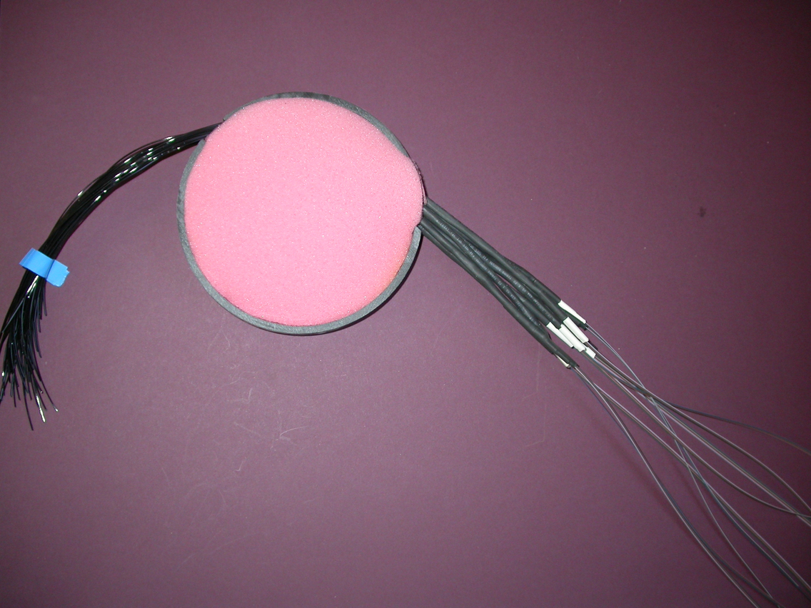
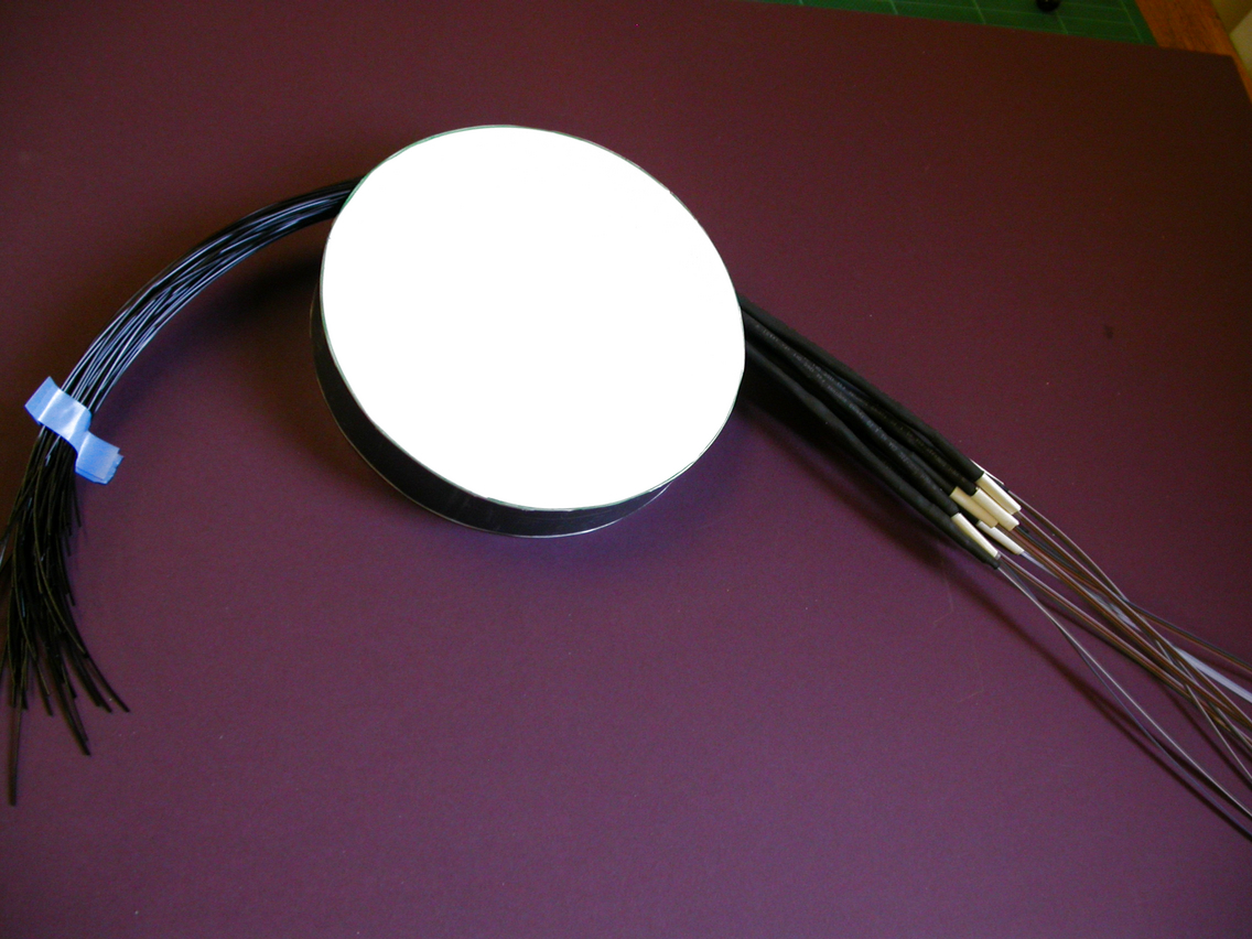
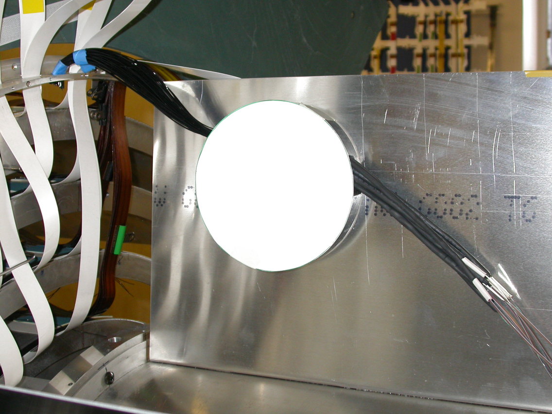
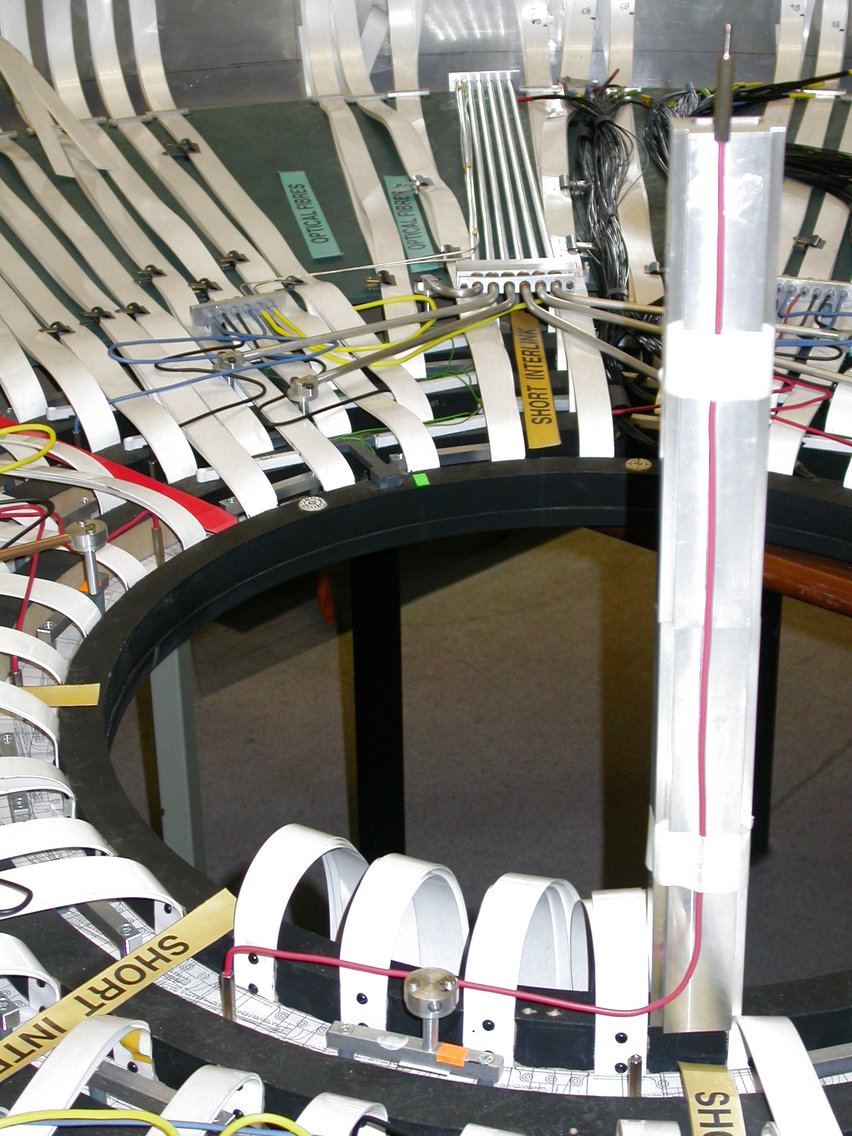
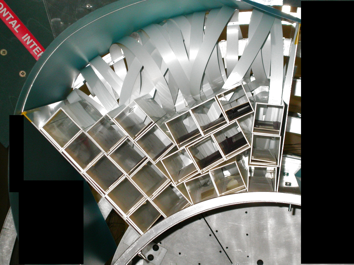
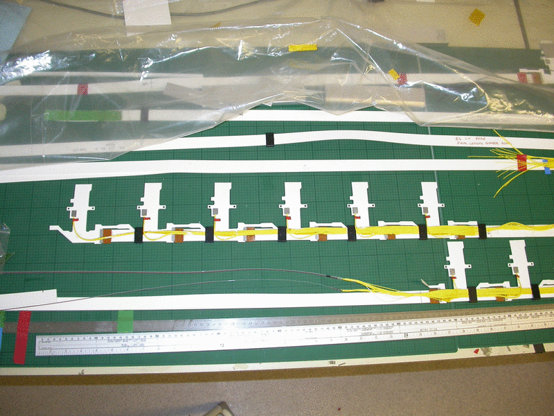
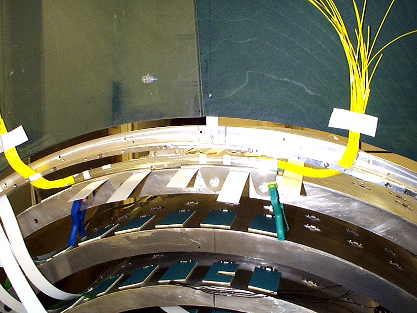
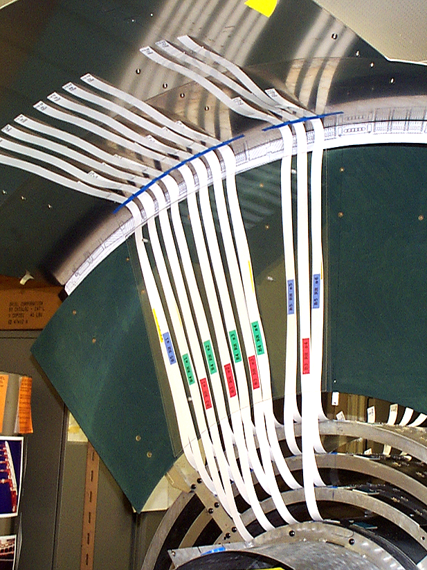
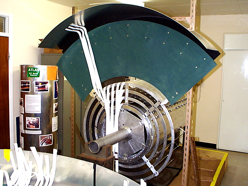
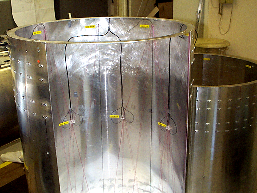
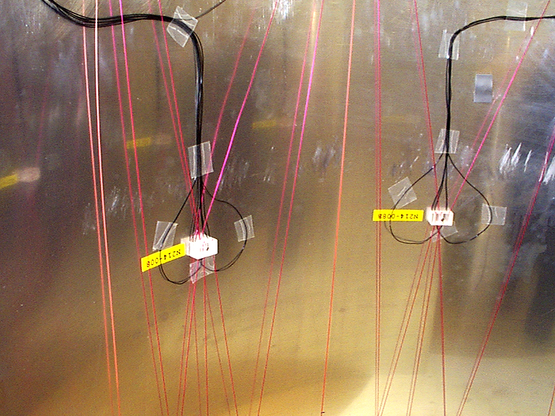
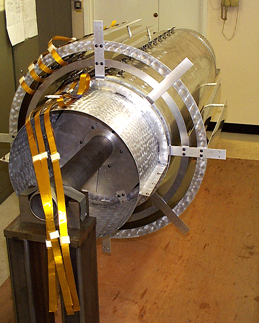
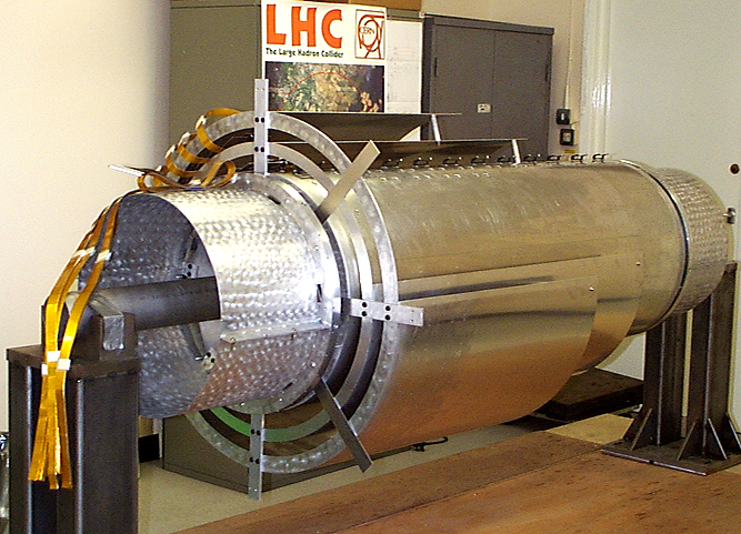
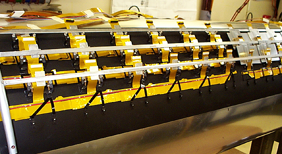
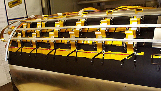
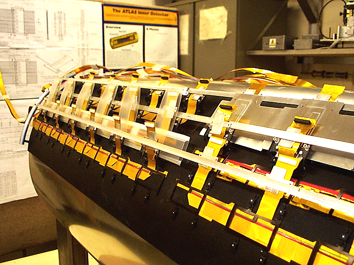
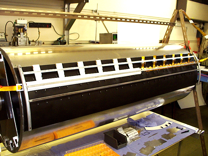
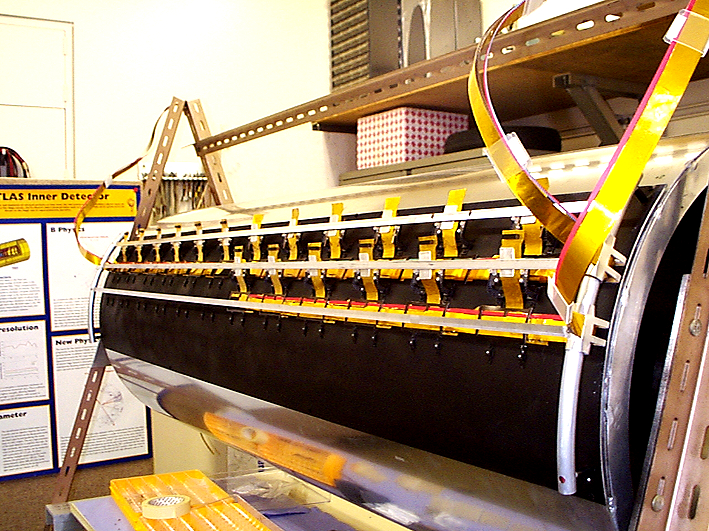
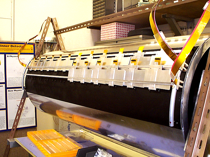
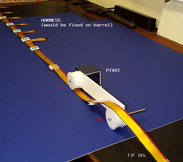
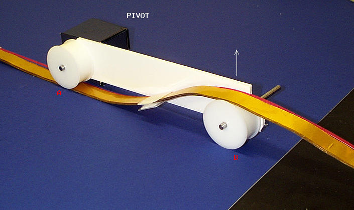
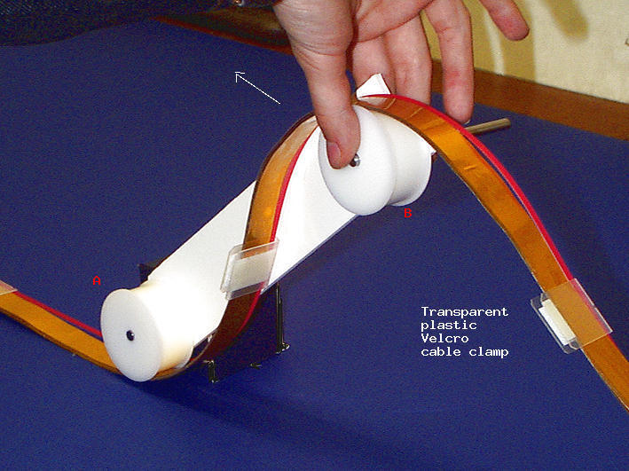
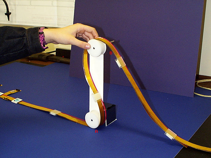
Real barrel assembly!
Here are some pics taken on 01.10.2003 at RAL of services cage trials using a TEST harness
on the REAL barrel 3
11.09.2003
New length cooling transition pipes have been modelled
If cooling transition pipes on one barrel all have to have the same length (different for each barrel) then all but one of the pipes will have to be overlength. This presents problems as the pipes will have to make more bends in order to take up the surplus length in an already congested area.
Here is a new set of photos illustrating the layout
NOTE: It will have to be proved that the pipe can be bent to the 'pattern' in situ -
we will use real transition pipe and special bending formers for the next attempt.
Barrel 6 has been left as is (see record for 11th August) as there is a special problem here during the 4 barrel installation sequence. It will not be possible to have all the pipes the same length.
11.09.2003
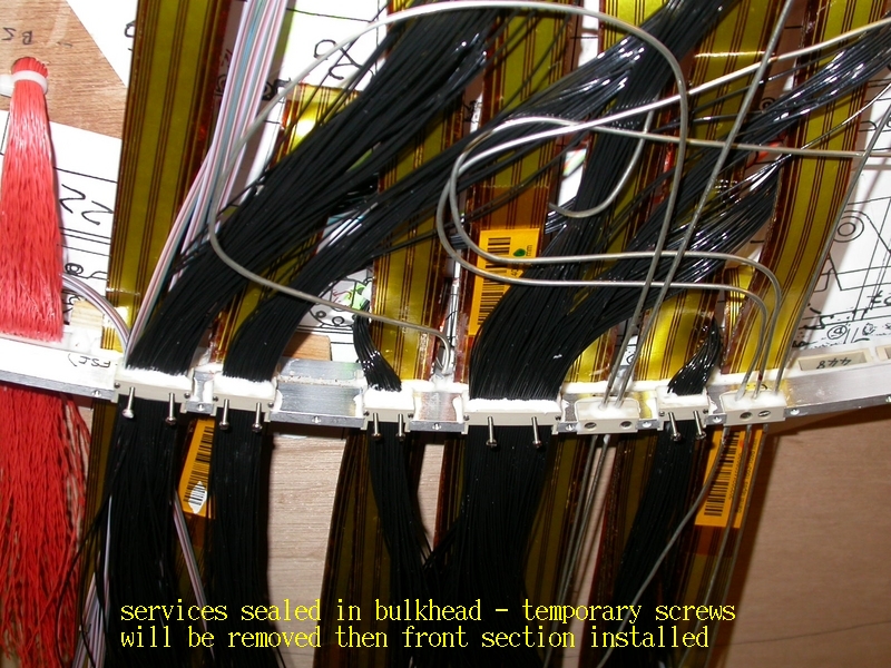
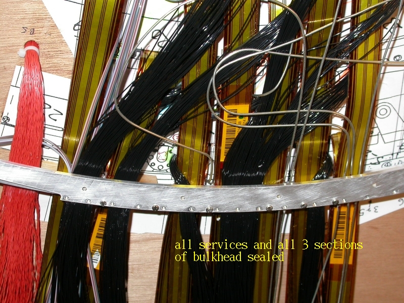
latest update of the TE bulkhead services leaktest/materials trials document
Here is the document revision number 1.5
01.09.2003
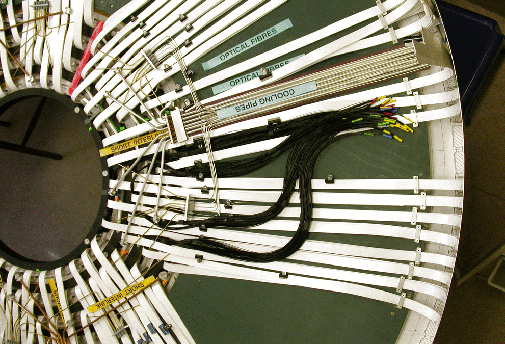
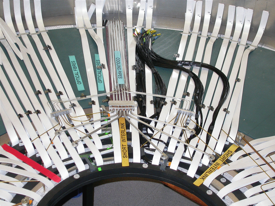
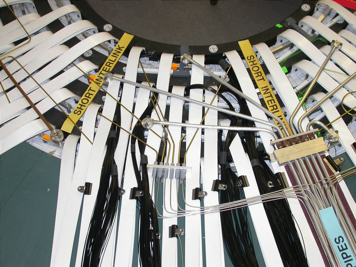
The proposed Barrel Numbering Scheme is illustrated
Here is a sketch with examples
13.08.2003
The order of harness installation is illustrated, together with fibre
routing and DCS wire routing orders
Here is a .ppt file with sketches showing harness installation orders, harness types and locations and DCS and fibre routing
on the barrel.
11.08.2003
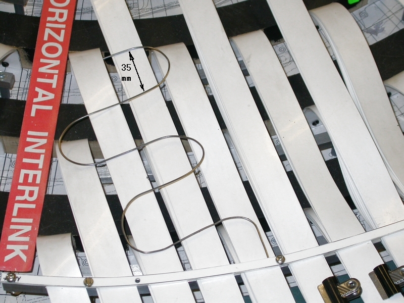
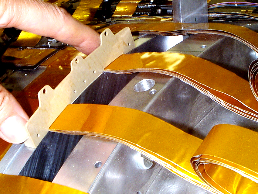
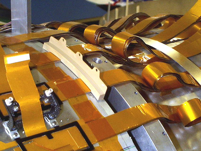
Cooling transition pipes and capillaries have been modelled.
This is however only a preliminary layout as capillary lengths may be standardised. A new set of transition pipes with realistic lengths will then replace
existing pipes on the model.
This replaces the old layout where capillaries extended from the barrel end through the Thermal Enclosure Bulkhead to terminate in connectors at PPB1.
Here is a series of photos of the model including all four quadrants in detail. Note that capillaries (see first quadrant) must join the exhaust pipes as soon as possible and that each pair of capillaries, although they may be from connectors in set one or set two must cross over the exhaust pipes to join alongside the exhaust pipe of the SAME cooling unit.
The full set will be included on the model later.
08.08.2003
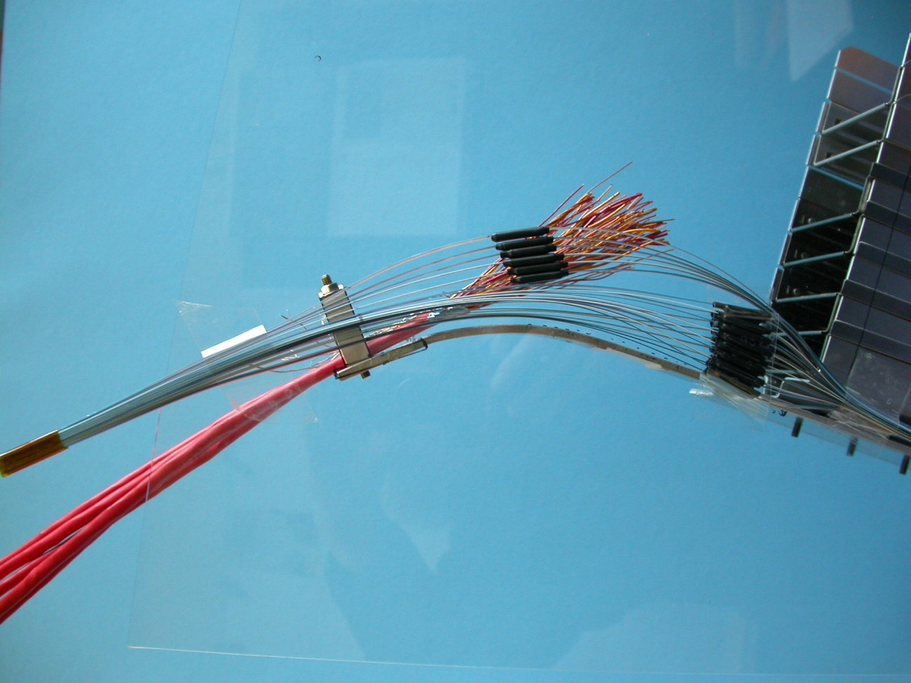
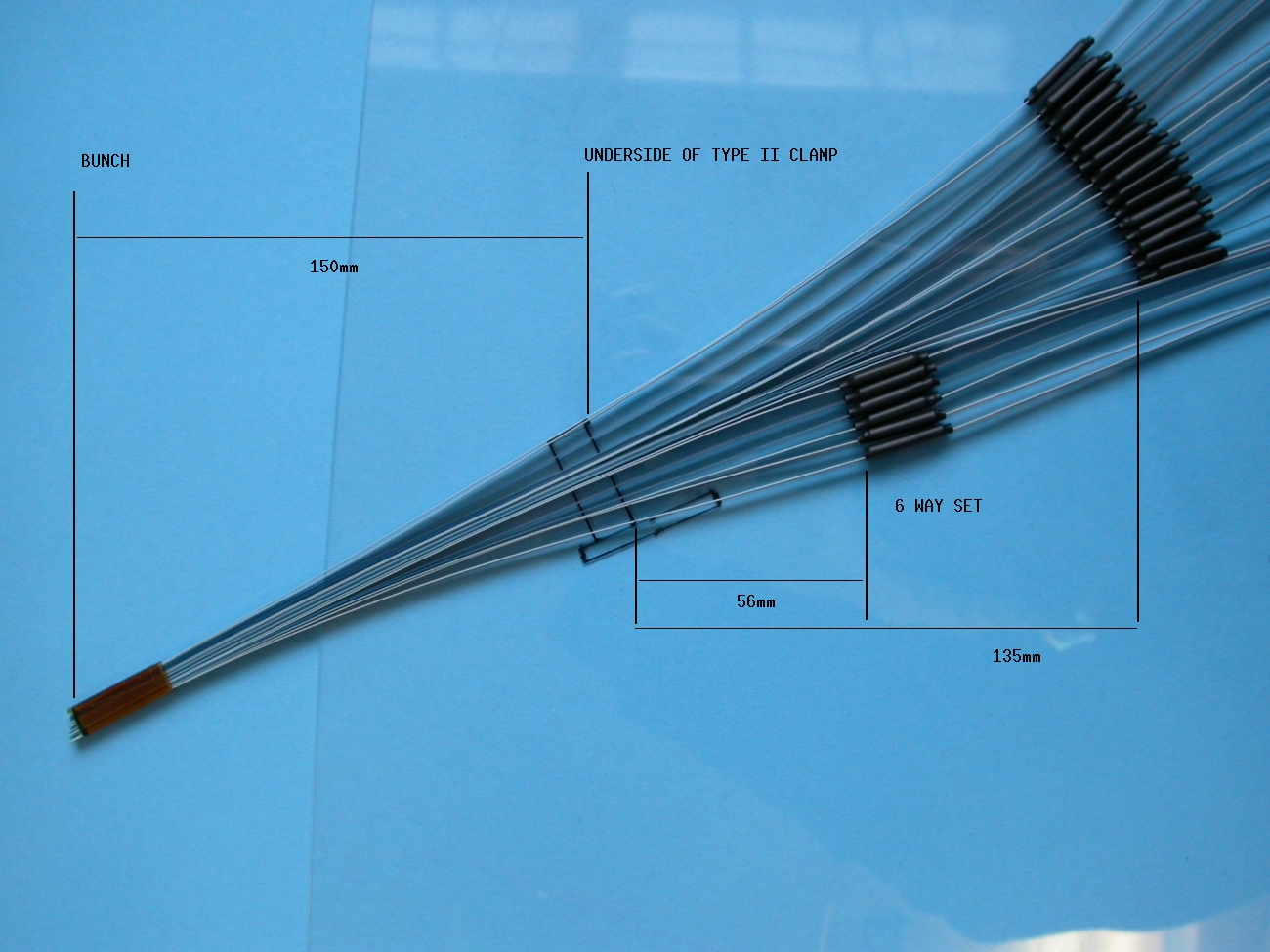
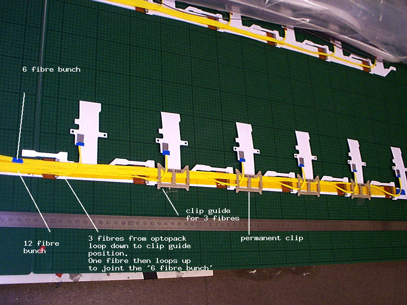
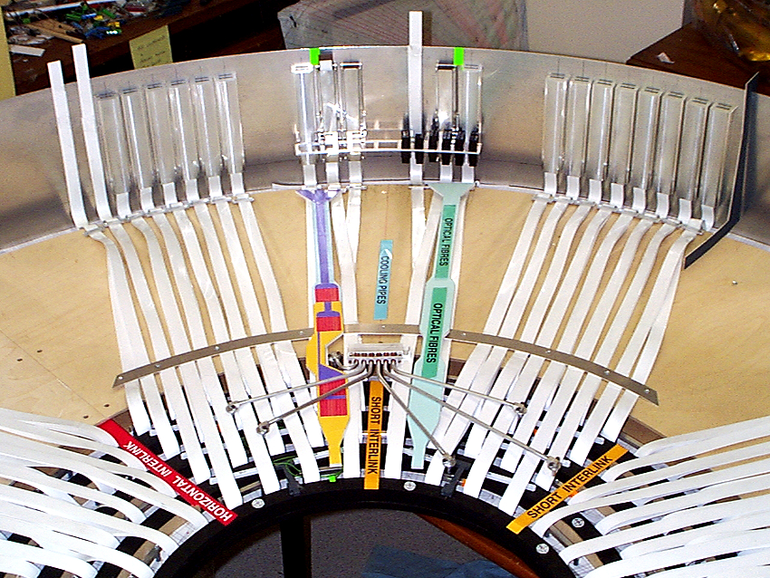
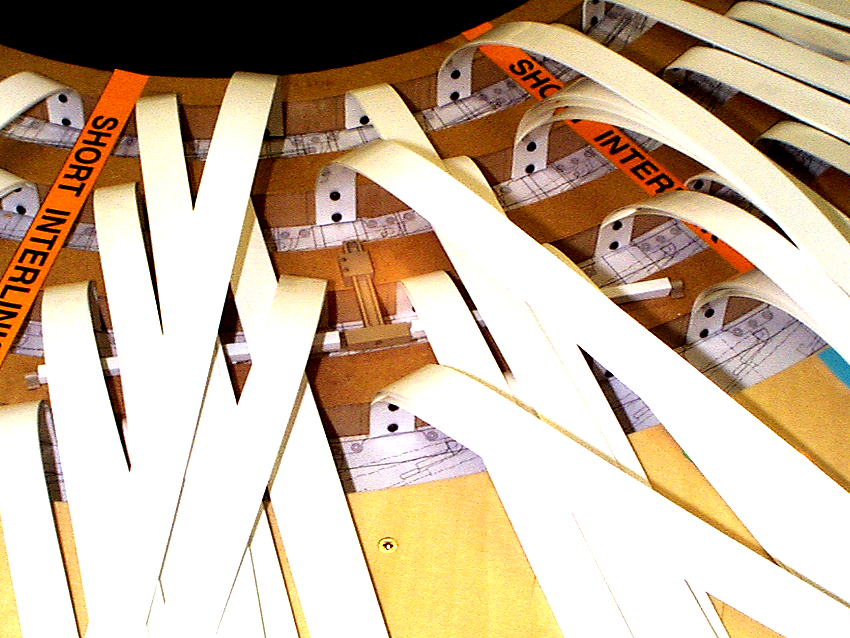
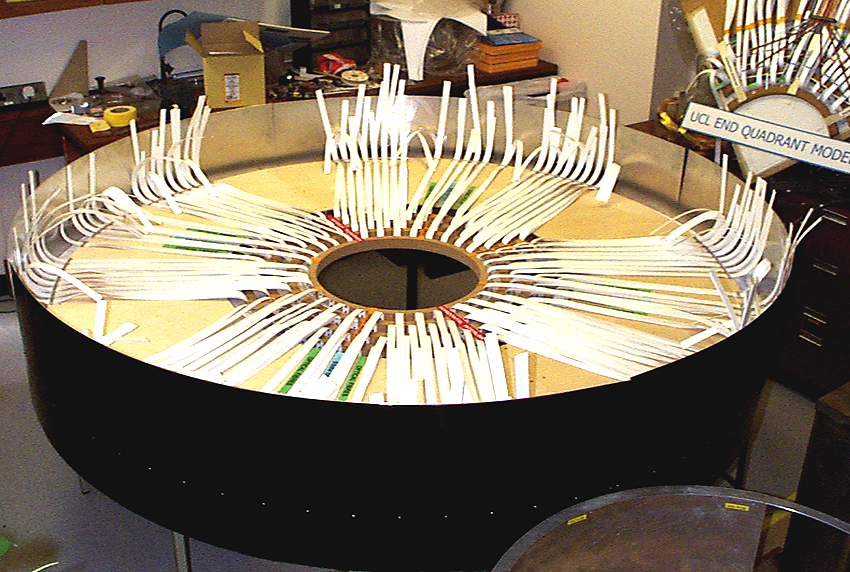
A trial layout of fibres (furcation tubing) has been made to represent fibres from ONE OCTANT ie 396 fibres in total. The new layout is necessary due
to the difficulty of fitting all 396 fibres in furcation tubing through a single 'slot' in the Thermal Enclosure Bulkhead. The fibres will most likely have to pass through the TE in four separate bunches at different places in phi - see sketch of 15.07.03.
Note that the ends of bunches have been left without splices or ribbon. These will be added later, as the real harnesses arrive at RAL - as the positions of the splices can vary. We can then build a representative picture of how the real layout will look.
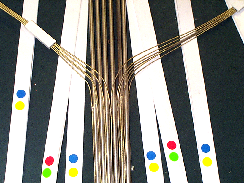
Here is a photo of the fibres coming through gaps in the LMTs, crossing the TE bulkhead area (there is no TE bulkhead on the model at present) and terminating at the stage where there would be a splice.
The end of each set of 6way and 12way fibres is colour coded:
B3 = red, B4 = green, B5 = blue, B6 = yellow.
The ends are in the position where they would be in order for the ribbon fibre
ends (not attached) to connect to the fibre PPB1.
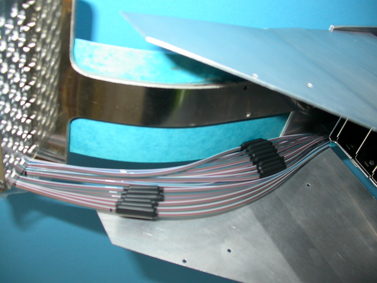
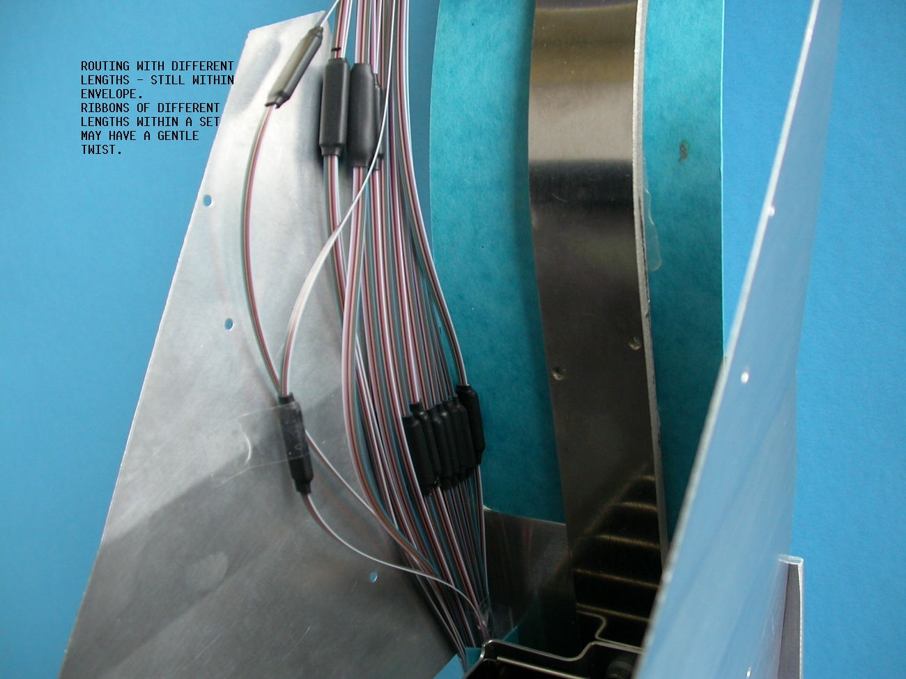
Here is another view of the same octant
and here is a close view of fibre bunches
The fibres in bunches now have to cross LMTs to reach the PPB1 position in phi. Here is a view showing how they keep well within the allowed envelope in Z, going over LMTs and under cooling pipes.
15.07.2003
There are 396 single fibres in furcation tubes per octant which have to pass through the Thermal Enclosure Bulkhead. The limited space available means that the fibres cannot now pass through in one single bunch but have to be split up into several bunches. This means that fibres have to deviate from the original route on the barrel ends.
A possible solution is to have four separate bunches spread out around the octant. (3 bunches of 90 fibres and 1 bunch of 126 fibres in the original 'duct'
where there is more space.)
Here is a .ppt file sketch of the possible layout
showing how bunches from various barrels are combined into 4 bunches going through the TE bulkhead.
This is a replacement of Version2 dated 15.07.03
Now also see photos - AUGUST 8th 2003 above where the bunching is as on the sketch.
17.06.2003 and updates
Leak testing and materials testing of sealant and grommets which allow services to pass through the thermal enclosure bulkhead are being done at UCL. A Report on the testing of the SCT barrel thermal enclosure bulkhead services sealant (B. E. Andersen, D. Attree, J. Fraser) can the found here. Tests are ongoing - updates of this .doc file will replace old versions.
21.05.2003
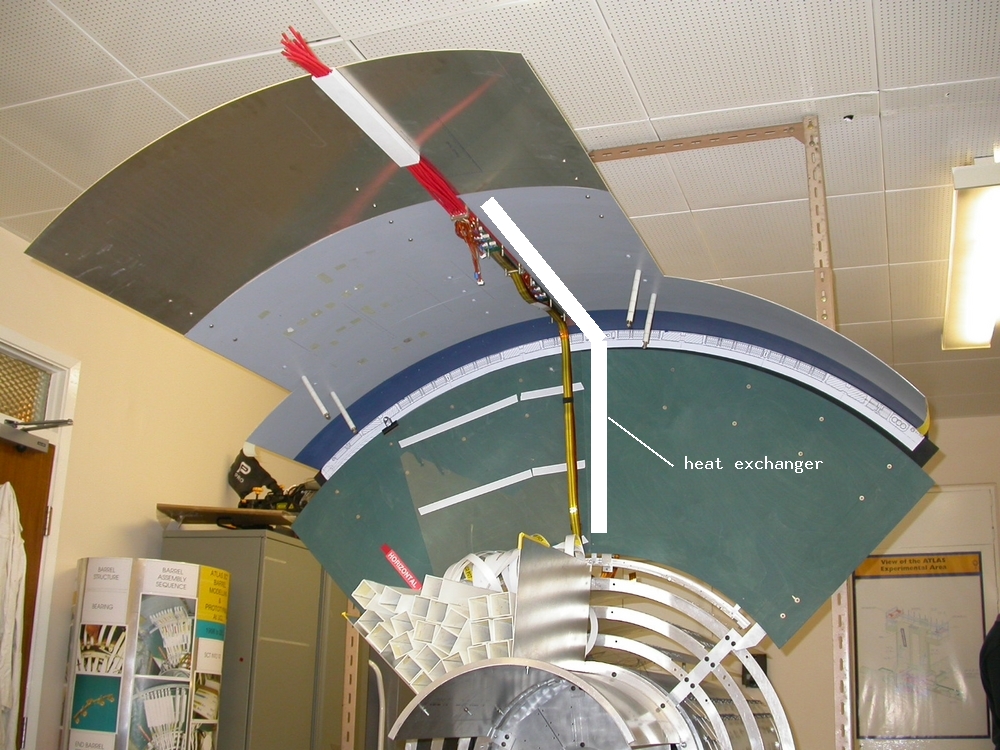
The barrel end cooling tube referencing disk as described in Ned Spencer's document of 21.04.2003 is being modelled at UCL. A first attempt is described here.
The document describes a foil annulus placed over the power tapes and cooling tubes. We think a foil in one piece may be unmanageable, so trials are done with the foil in sections for each quadrant, however it is possible that two halves would work. The foil used for modelling was 100um kapton/Al but the real foil to be used is 100um total with Kapton/Al/Ni/Au layers (exact composition not known).
This shows 3 tab links (RH section of quadrant)from the foil to the heat-spreader plate tabs which would be pre-soldered to the heat-spreader plate under the tapes. The tabs are placed as evenly as possible but have to avoid high tape stacks either side of the cooling pipes and wide fibre ducts (not shown) next to the tape stacks.
This is just a possible solution.
Both the heat-spreader plate tabs and the foil tabs are 70mm long x 10mm wide. The tabs from the foil have to pass through the thermal enclosure bulkhead with the power tapes so have to be pre-aligned at the same angle as the tapes.
Their positions on the outer edge of the foil (B6 outer diameter) are symmetric about the cooling pipes and are the same for each quadrant.
The heat-spreader plate tabs are positioned so that they emerge through the tapes at right-angles to the foil tabs. This facilitates the join between the two tabs and allows for some play in the looped tabs. A solder joint here would be difficult - it may be best to use special clips 10 x 10mm surface area.
The 3 tab links on the LH section of the quadrant are shown here
Here is a view of the whole quadrant showing all 6 tab links
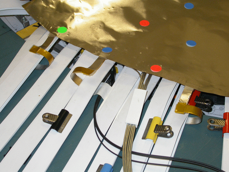
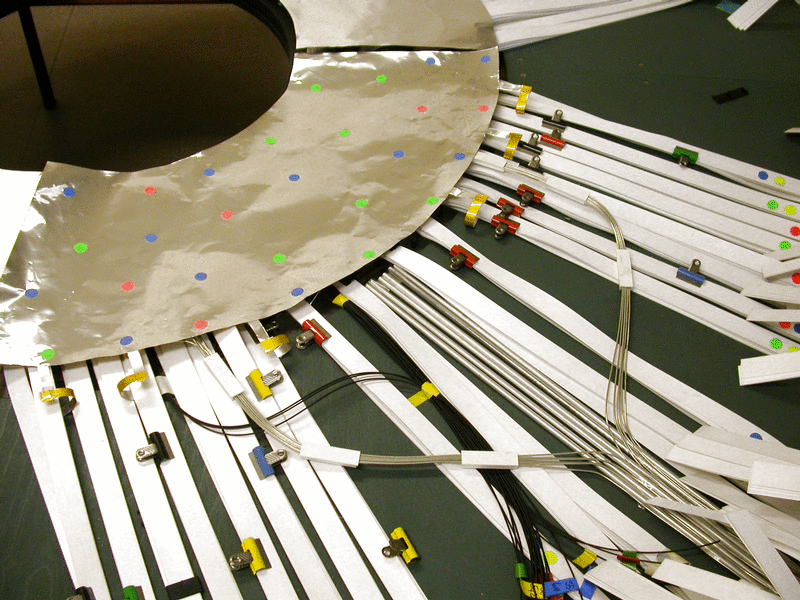
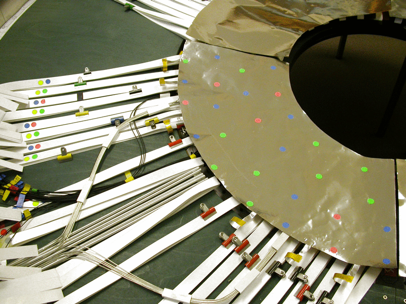
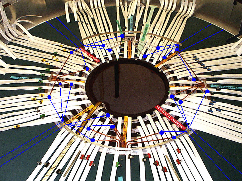
Another view showing the foil section for one quadrant marked with colours where litz wire connections would have to be made between cooling pipes under the foil and the outer surface of the foil.through pinched holes
The RED dots represent litz wire connections from the cooling exhaust manifolds
The BLUE dots represent litz wire connections from the input capillaries
The GREEN dots represent litz wire connections from the cooling return loops
NOTE that the positions of these are different for each Quadrant. Here there are 6 exhaust, 12 capillary and 10 return loop connections.
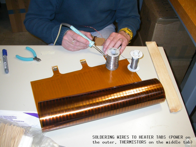
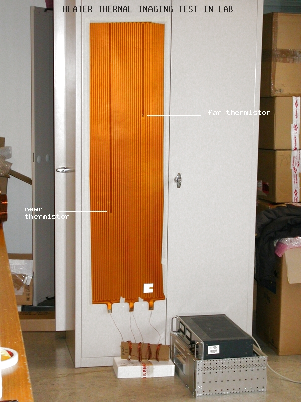
An attempt was made to solder the litz wire (20 wires) to the gold surface of a sample of the REAL foil (Kapton/Al/Ni/Au) threaded through a 6mm diameter hole, with wires fanned out on the surface.
Here is a view of the underside of the solder join showing the Kapton surface of the foil. The other end of the litz wire is soldered to an eyelet tab. The tab with wire would be pre-attached to the cooling pipe.
Here is a view of the solder area from the gold side of the foil. Note that there is solder/flux splatter. More trials need to be done using wire with chemically cleaned ends and some means of flattening the splayed wire ends. It may help to pre-tin the surfaces.
here is a view of all four quadrants. A large foil area may make it difficult to thread litz wire connections through from underneath.
We have to prove that soldering to this foil will not cause damage to the power tapes underneath.
14.04.2003
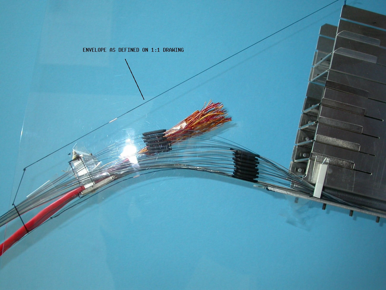
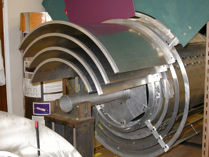
All 4 barrel services cage 'envelopes' were tried out on the 4 barrel model
Trials were done in order to illustrate the amount of space available if services cages were all left on each barrel at the time of assembly.
here is a view of the services cage 'envelope' - without services - on barrel 3 only
Here is a view of all 4 services cage envelopes - without services attached to the 4 barrel tooling rings
09.04.2003
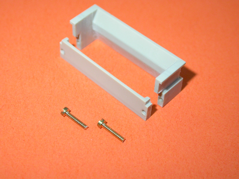
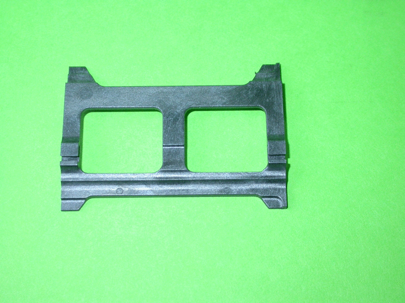
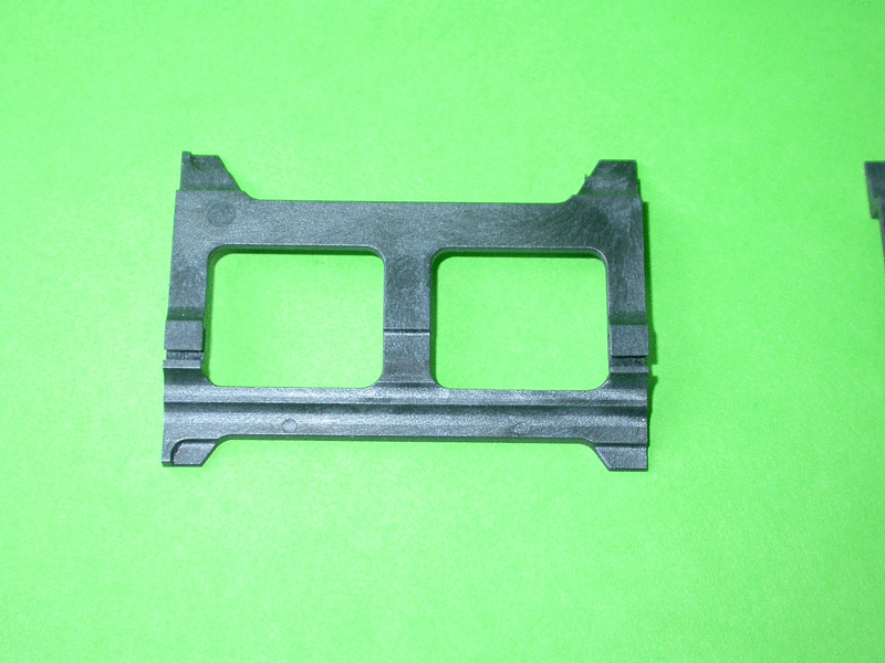
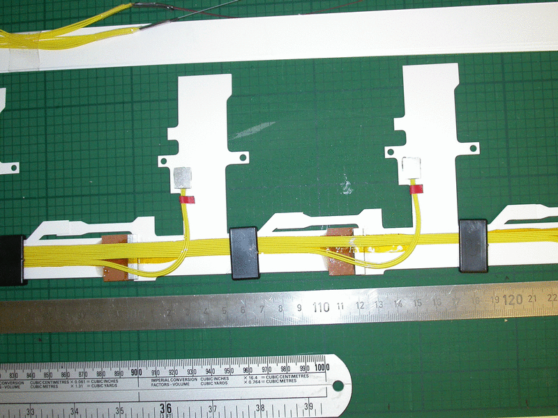
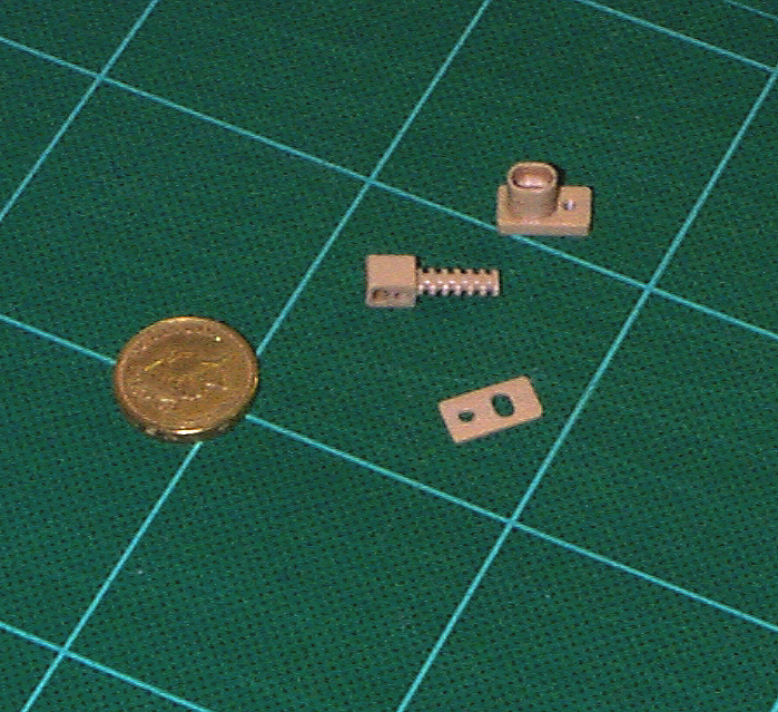
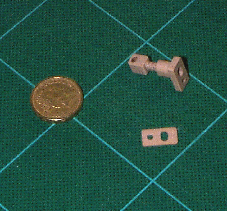
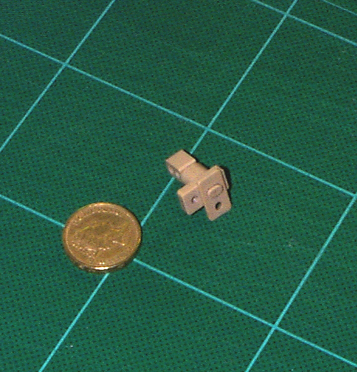
The first final harness clips have been made
The clips are made by moulding VECTRA A 130. The moulding has proved accurate
and within spec. with only a very small amount of finishing work necessary.
Here is a photo of the RH harness clip
Here is a photo of the LH harness clip
See also clip type, order and location on barrel
NOTE all types of clip are the same for each barrel
13.03.2003
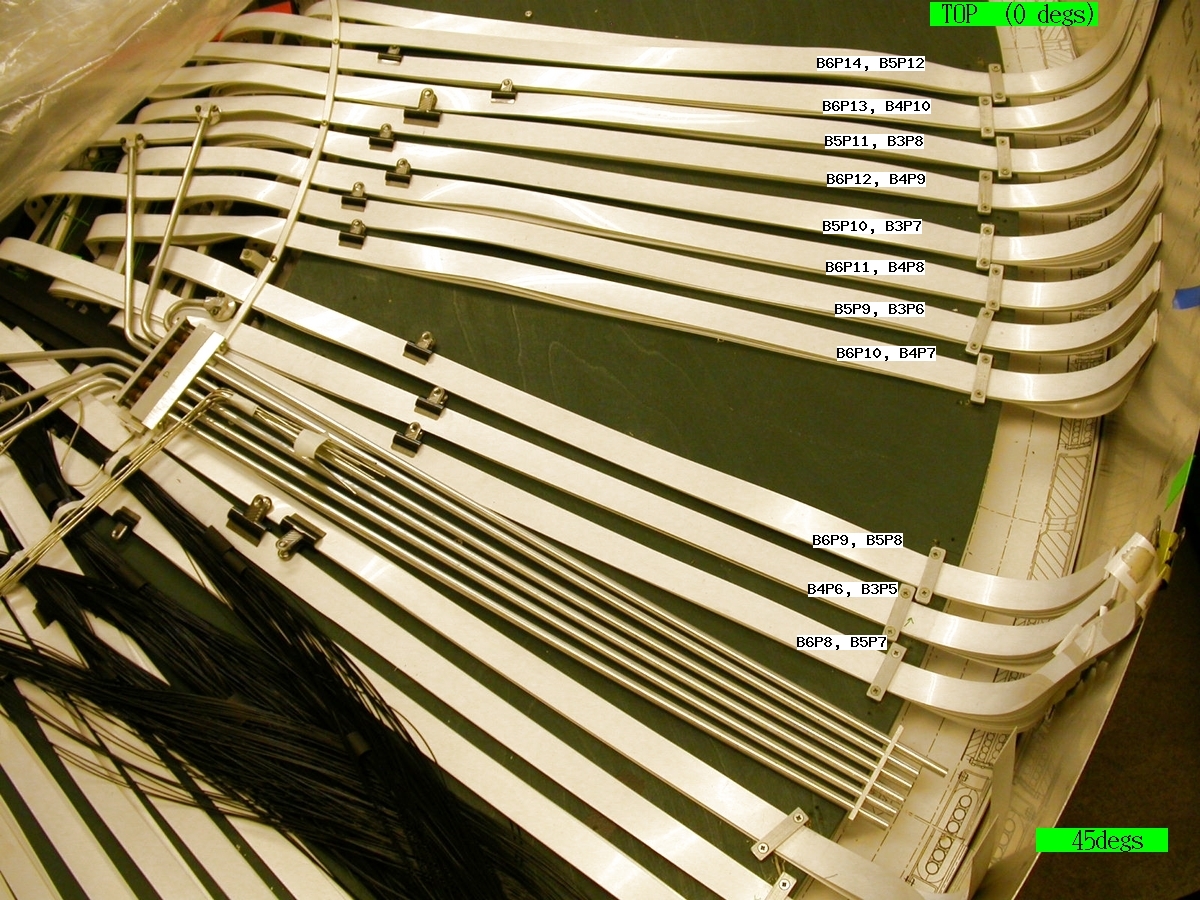
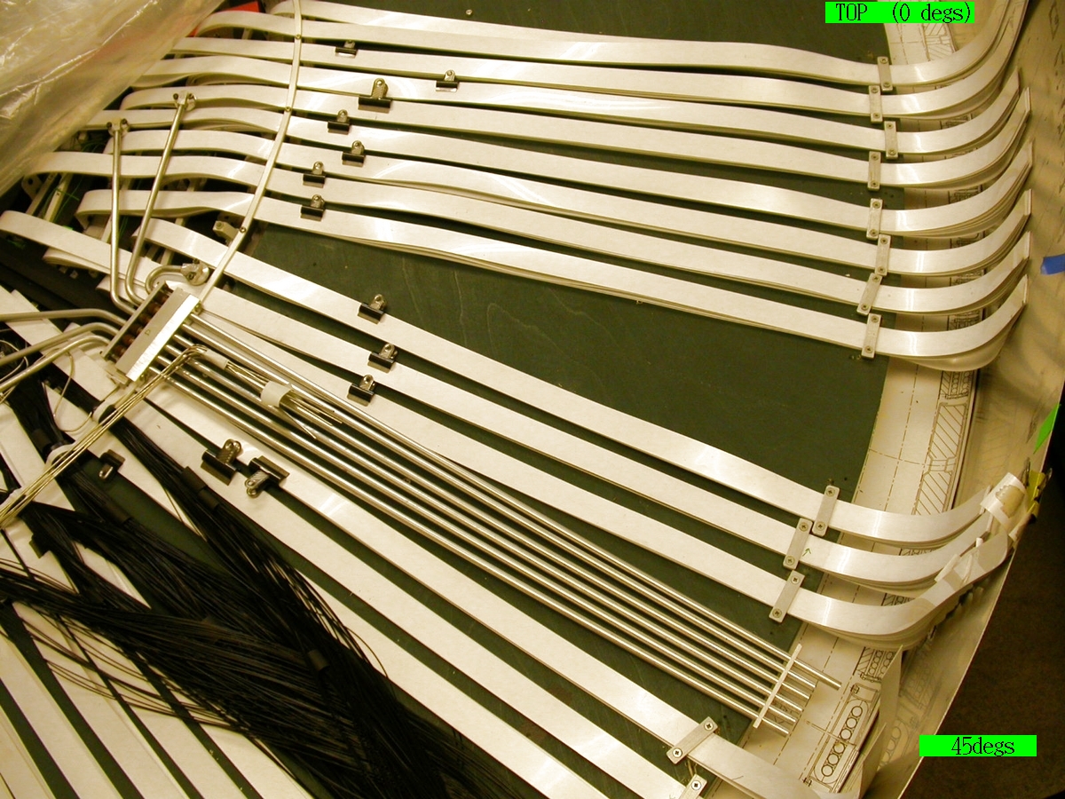
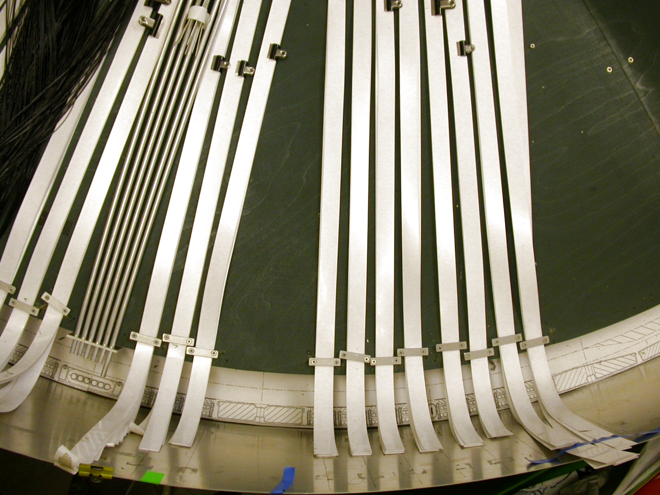
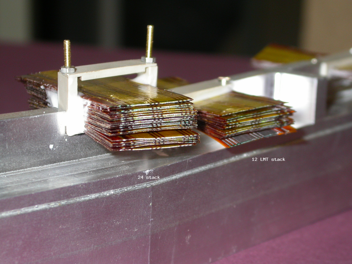
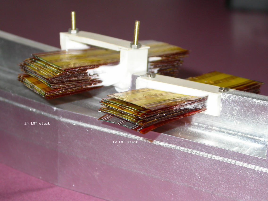
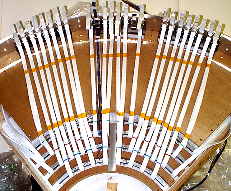
It was necessary for people at CERN to know the mapping of the LMTs from the 4 barrel assembly in the SR building so that cabling for testing could be installed
Here is the full 360 deg LMT mapping diagram for one barrel end showing the layout of each harness for each barrel and quadrant.
NOTE that the naming of Quadrants and harnesses ('staves') may be different from the 'physics' terms for the same regions!
27.02.2003
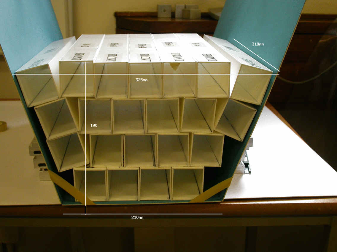
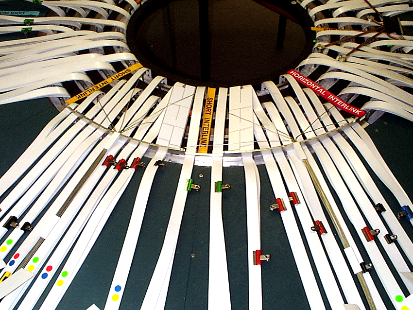
The temporary PPB1 connected to the permanent PPB1 forms a long box shape approximately 318mm long x 42mm x 26mm.
Each LMT harness terminates in such a box, therefore there are 22 per octant. Accommodating 22 of these during testing and installation (allowing access for disconnecting and reconnecting) may be a problem as they would have to occupy no more than 1/8th of the space around the barrel. Trials with 22 model connector boxes were done.
Here the LMTs are hung on a temporary support with the connector boxes - these would be fixed to the support rather than left looseduring the testing phase.
It can be seen that the 22 boxes occupy a large amount of space but the arrangement could allow for some overlapping
Here is a diagram of the possible arrangement of the connector boxes during testing (.ppt file).
See also note of 17.01.2003 for layout of LMTs from TE
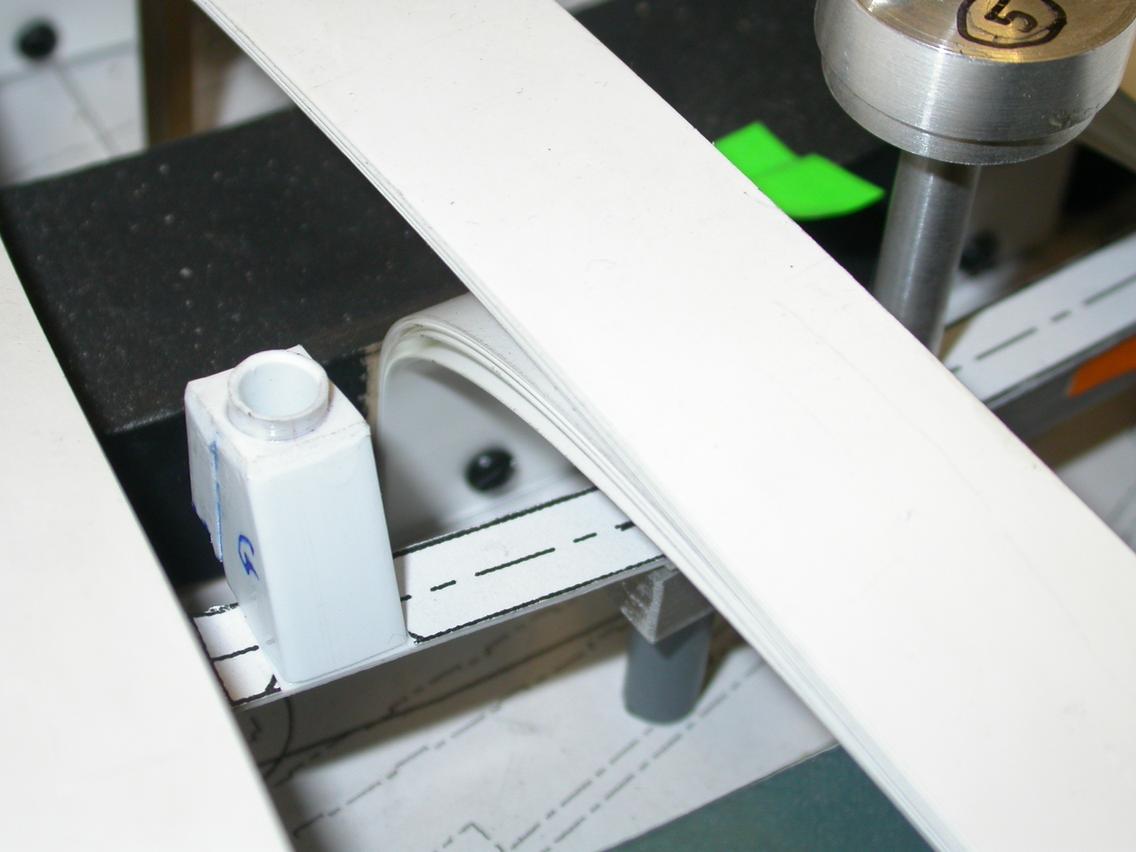
During the installation phase, the boxes will have to be stacked together within a very limited space inside the radii of the Thermal Enclosure, at the barrel ends.Here the 22 connector boxes for one octant are stacked as closely as possible. As LMTs have to be folded within the same space there does not appear to be sufficient space for a total of 176 within the constraints at the barrel end. Removing the Temporary PPB1s may be the only solution, leaving the permanent PPB1s and LMTs in the stack.
09.02.2003
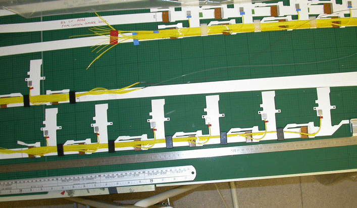
Diagrams showing the permanent harness clips locations in Z along the barrel have been produced relating harness clip type with it's location
Here is a diagram of the clip orders and types (.ppt file) with recess dimensions, numbers of fibres and LMTs served by the clips.
Here are diagrams of the LH and RH clip locations - distances from Z=0 (.ppt file).
27.01.2003
Barrel 3 end clamps fitting
The manufactured version of the Barrel 3 end clamps which serve as LMT clamps, cooling manifold brackets and fibre/DCS wire routing were found to require packing of various thicknesses to produce an efficient clamping effect during trials on B3 when at Geneva. Here is a diagram of the packing required, with alternative arrangements (.ppt file) as a result of trials done on the barrel 3 cylinder at Geneva.
NOTE that this should not be necessary for barrels 4, 5 and 6. Clearance between barrel surface and inner radius of clamp can be minimised and the LMT recess
should have a radius on each inner corner rather than a sharp right angle to effect better clamping.
24.01.2003
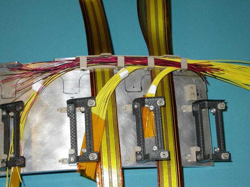
Barrel end clamps - fibre and DCS cable routing
DCS cable from temperature and other monitors on the barrel has to be routed around the barrel end circumference sharing the same routing space on the barrel end clamps as the readout fibre but exiting at different points from the fibres.
Here is a photo of the trial done to see how many DCS cables (twisted pairs, each single cable 0.54mm thick) will fit together with 3 sets of 18 fibres from 3 harnesses in the same space. 12 twisted pairs of DCS cables could be fitted under the clamp on the right which holds the maximum number of sleeved fibres (54).
here is a diagram showing the optimum routing of DCS cables (.pptfile) from the barrels, through the TE bulkhead and out to the DCS connector PCBs at PPB1. The best position for the DCS connector PCBs would be at 90 degs from the horizontal, with cables routed straight outwards from the TE bulkhead.
Any surplus cable can then be wound up and stored flat in a suitable location between the TE bulkhead and PPB1.
23.01.2003
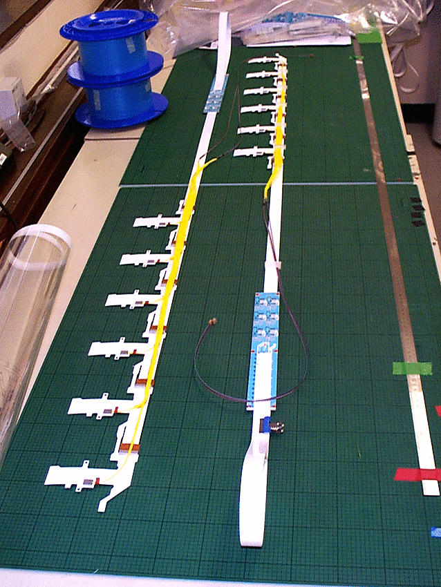
Latest Harness layout reverts back from layout of 30.08.2002 to the basic layout of 09.06.2002, with the 3 fibres from each dogleg running together then separating into 2 readout and 1 TTC fibre sets before the fibre PPB1.
View of whole LH model harness
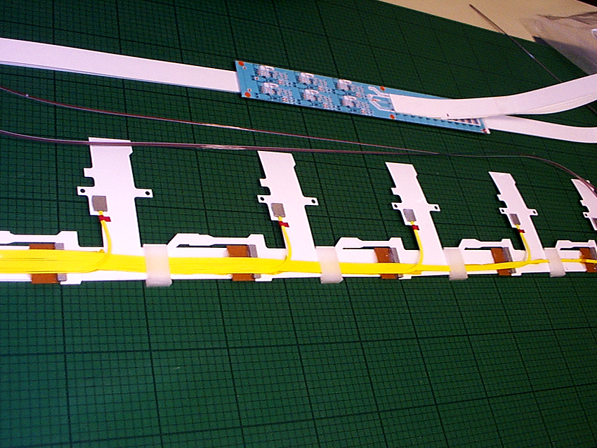
Close-up vierw of 2LH doglegs and fibres held in position with Temporary clips (moulded plastic).
Another close-up but with fibres held by the Permanent Clip made of PEEK. Note that the fibres runclose together along sticky Kapton tape which keeps them in ribbon form.
View of whole RH model harness
View of part of RH harness. Note that the fibres are routed as close to the upper edge of the harness as possible.
Close-up of 3 doglegs showing fibre loop with temporary clips.
View of RH harness with Permanent PEEK clips
17.01.2003
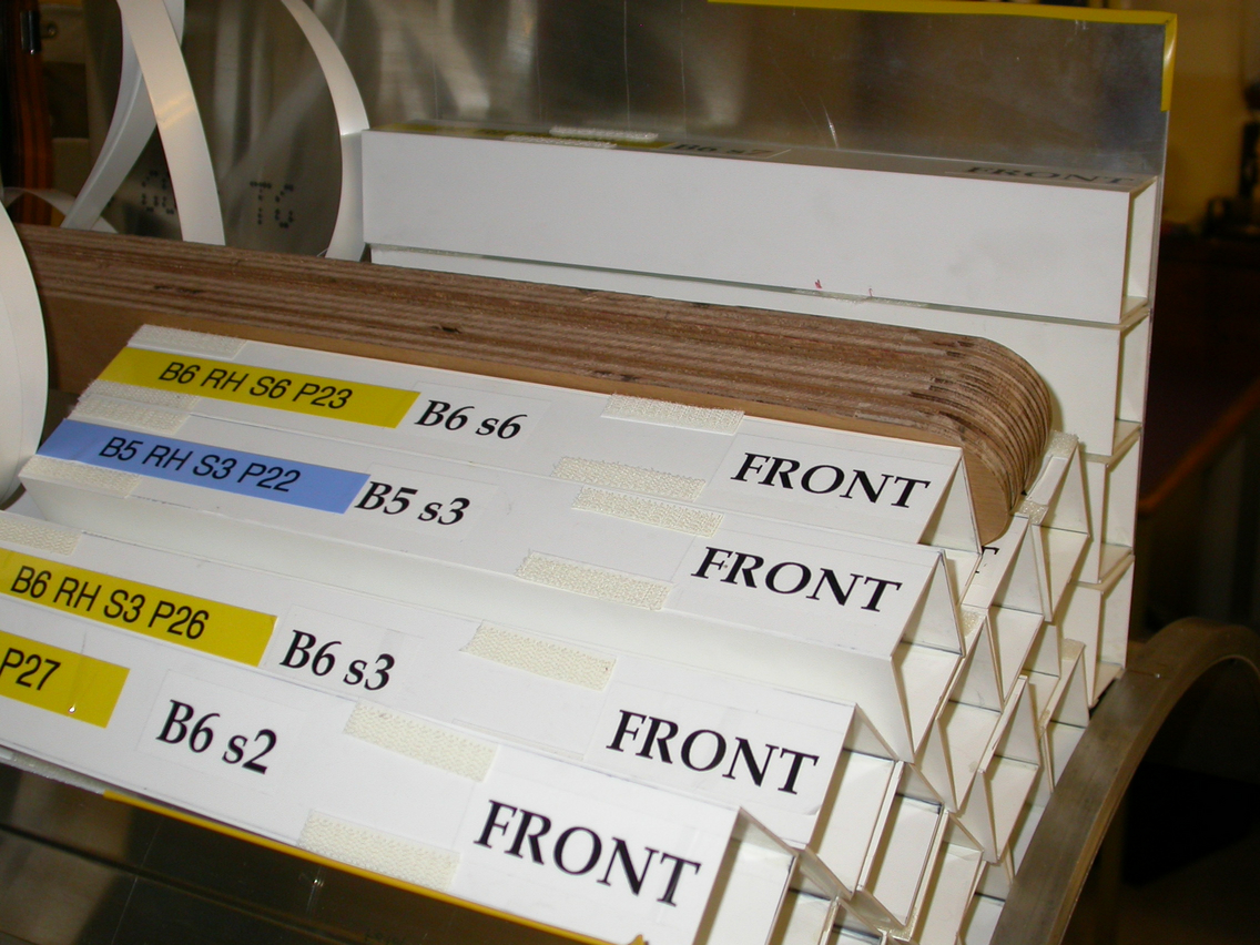
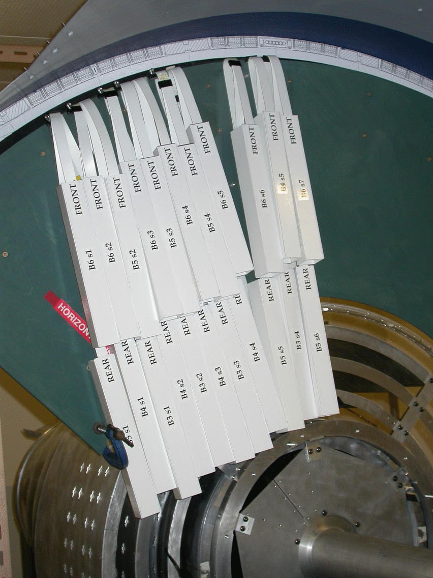
Low Mass Tape Configuration after 4 Barrel Assembly
Photos of the sequence in which the LMTs should be connected at PPB1 One octant at the +Z end is shown. Note that the PPB1 boards are represented by material with the correct length and width and the harness numbers and 'stave' (position in phi) numbers are clearly shown on each.
Here is a diagram showing the schematic layout of sets of LMTs at the TE and PPB1 for one octant (.ppt file).
05.12.2002
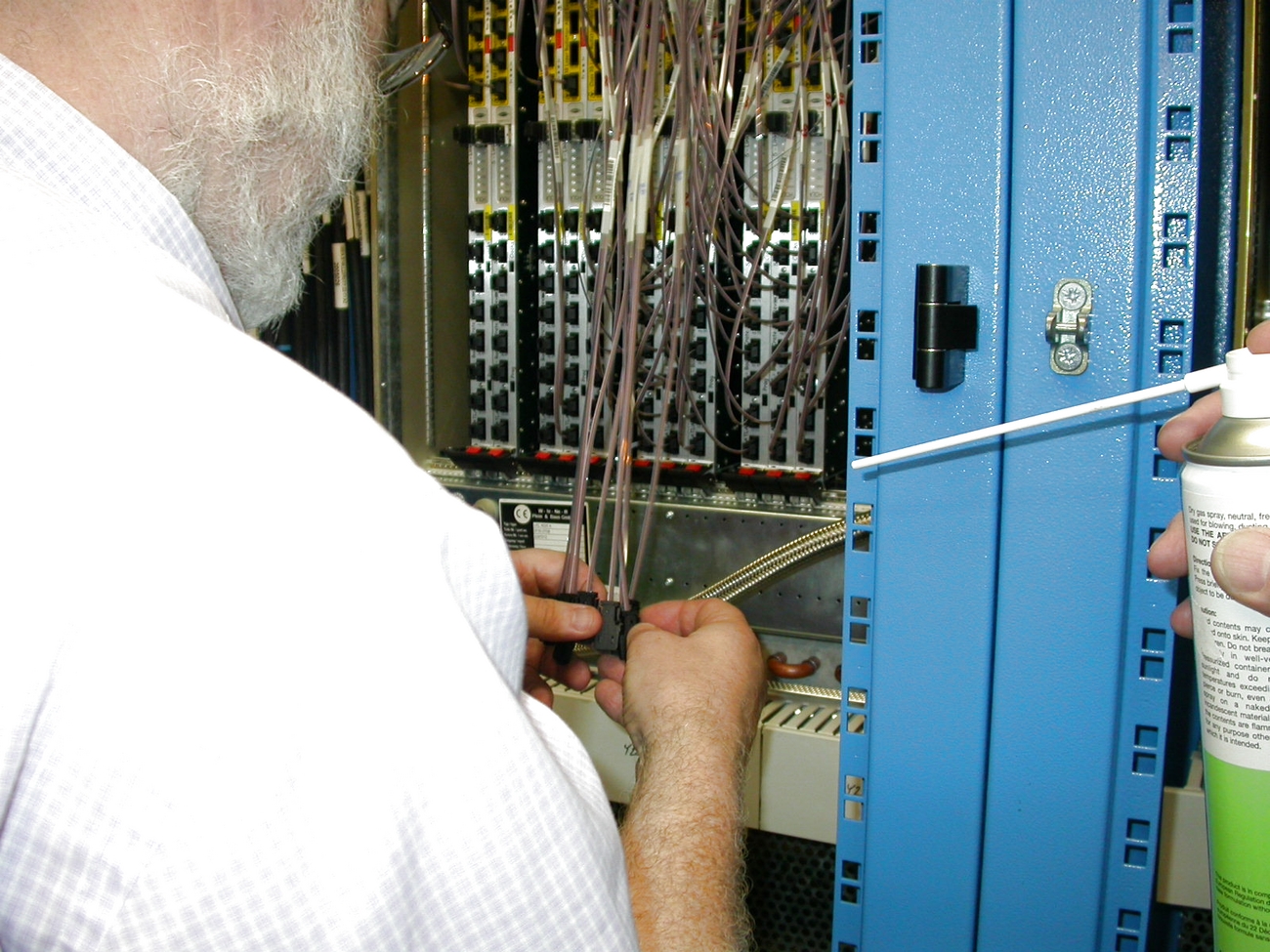
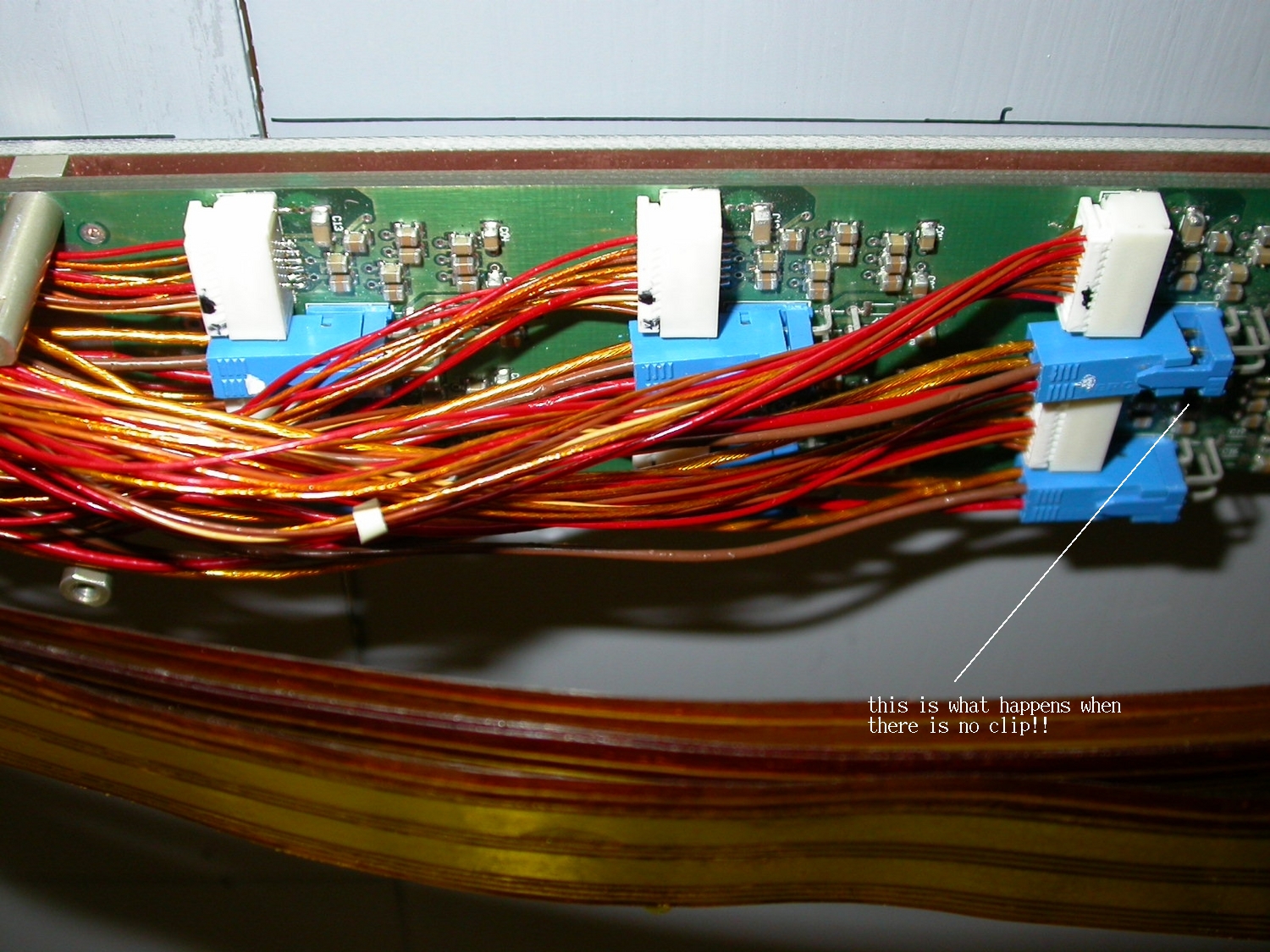
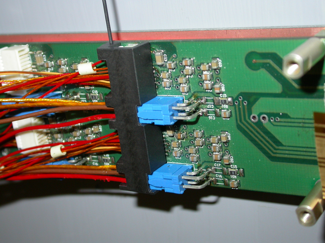
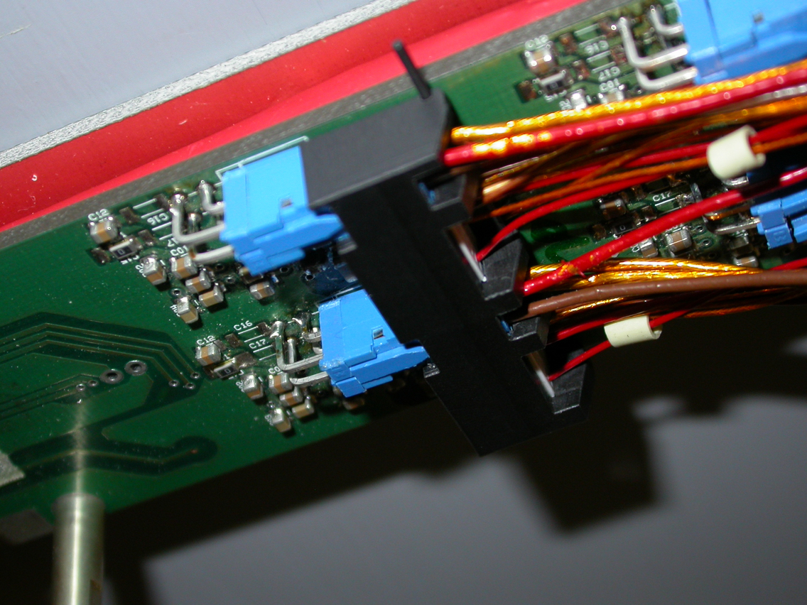
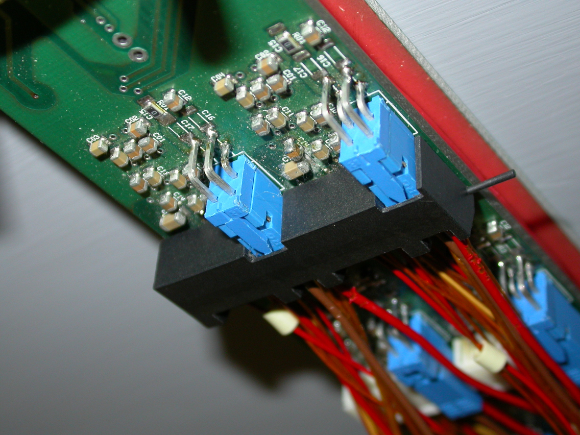
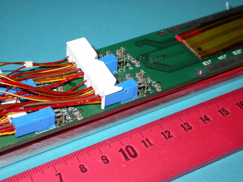
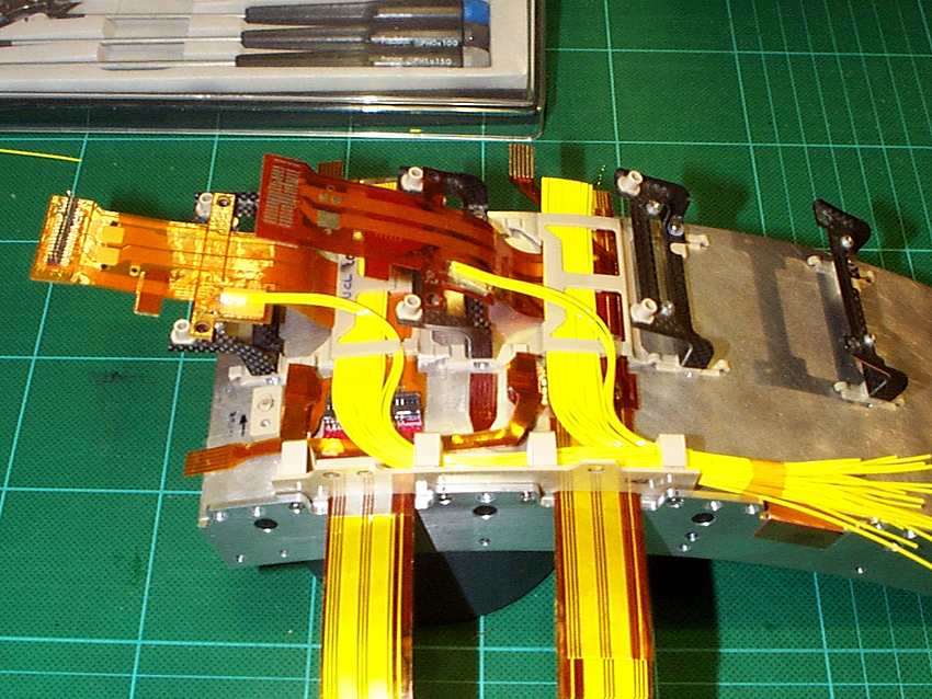
Further work on trials with PPB1 boards and connectors
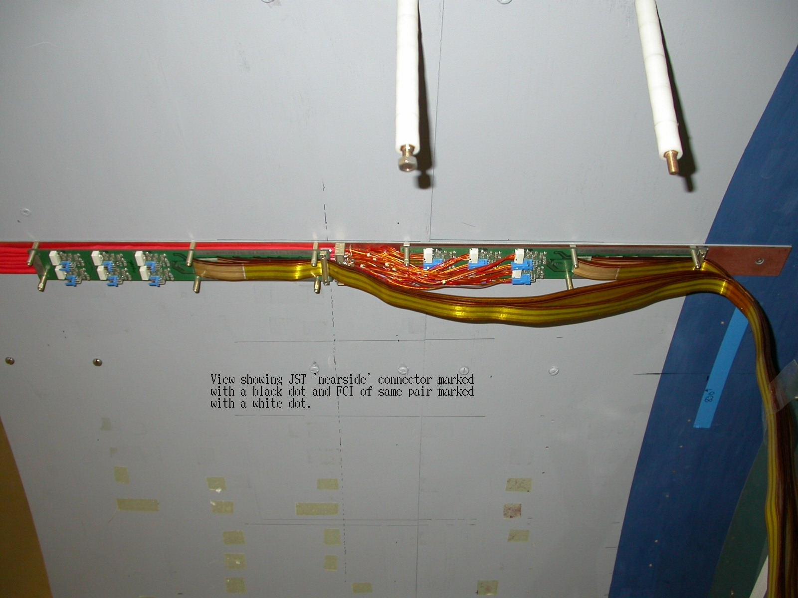
This shows the LMTs going over the connectors and type II cables - Note that one of the FCI connectors has become disconnected.
We have found that the power (FCI) connectors (blue) are easily disconnected - any slight movement of a stiff power cable can cause this. To solve the problem, a special connector clip was designed. This fits over one row of four mated connectors (2 FCI and 2 JST) and should, provided there is also adequate strain relief on the cables, prevent any movement or disconnection of both FCI and JSTs.
Here is a photo of the clip in place over the connectors
and another view from the side
04.12.2002
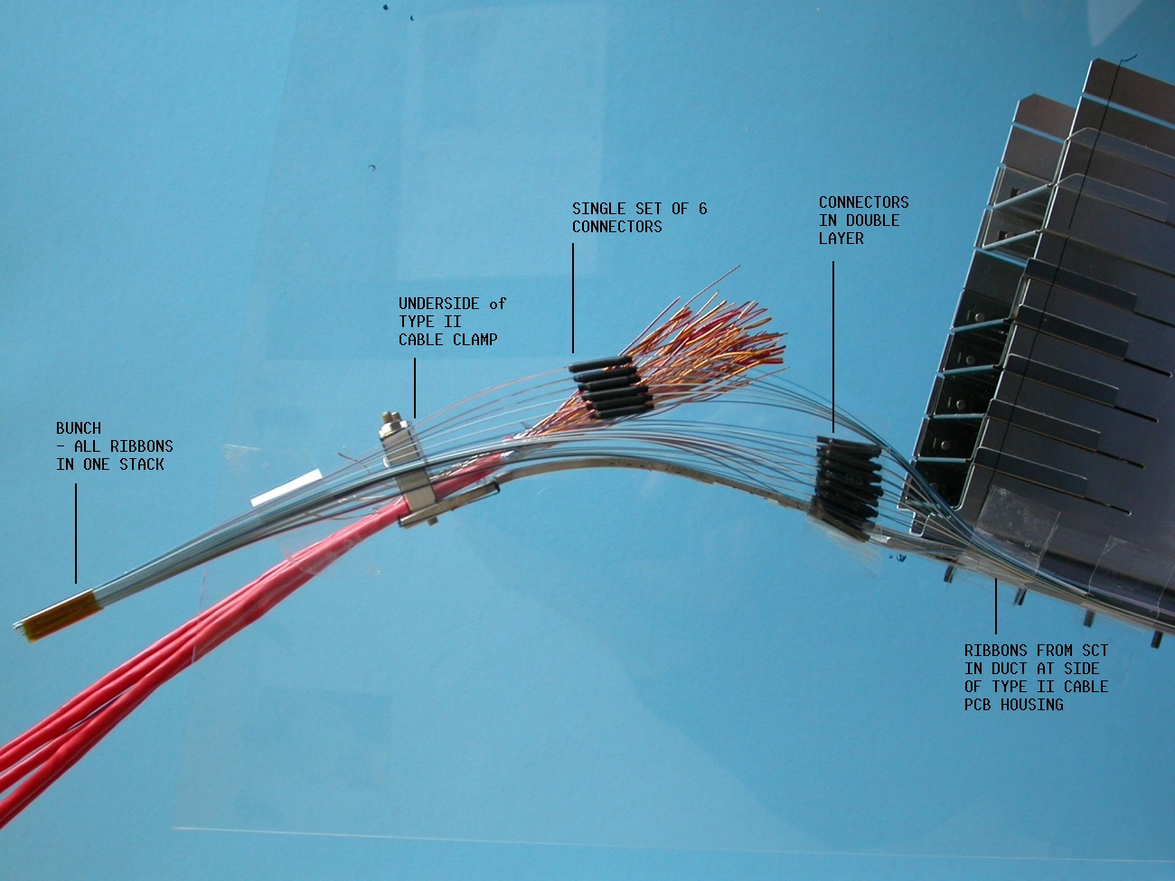
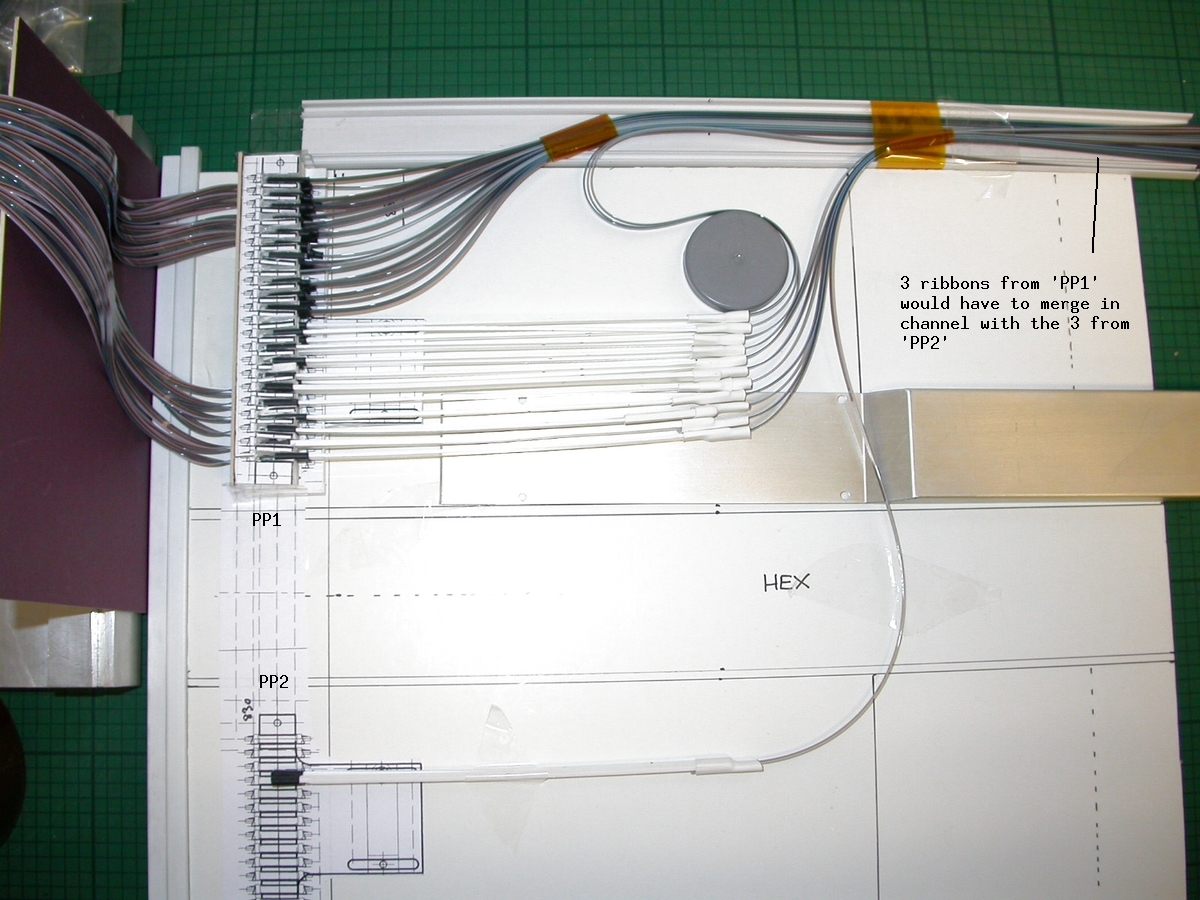
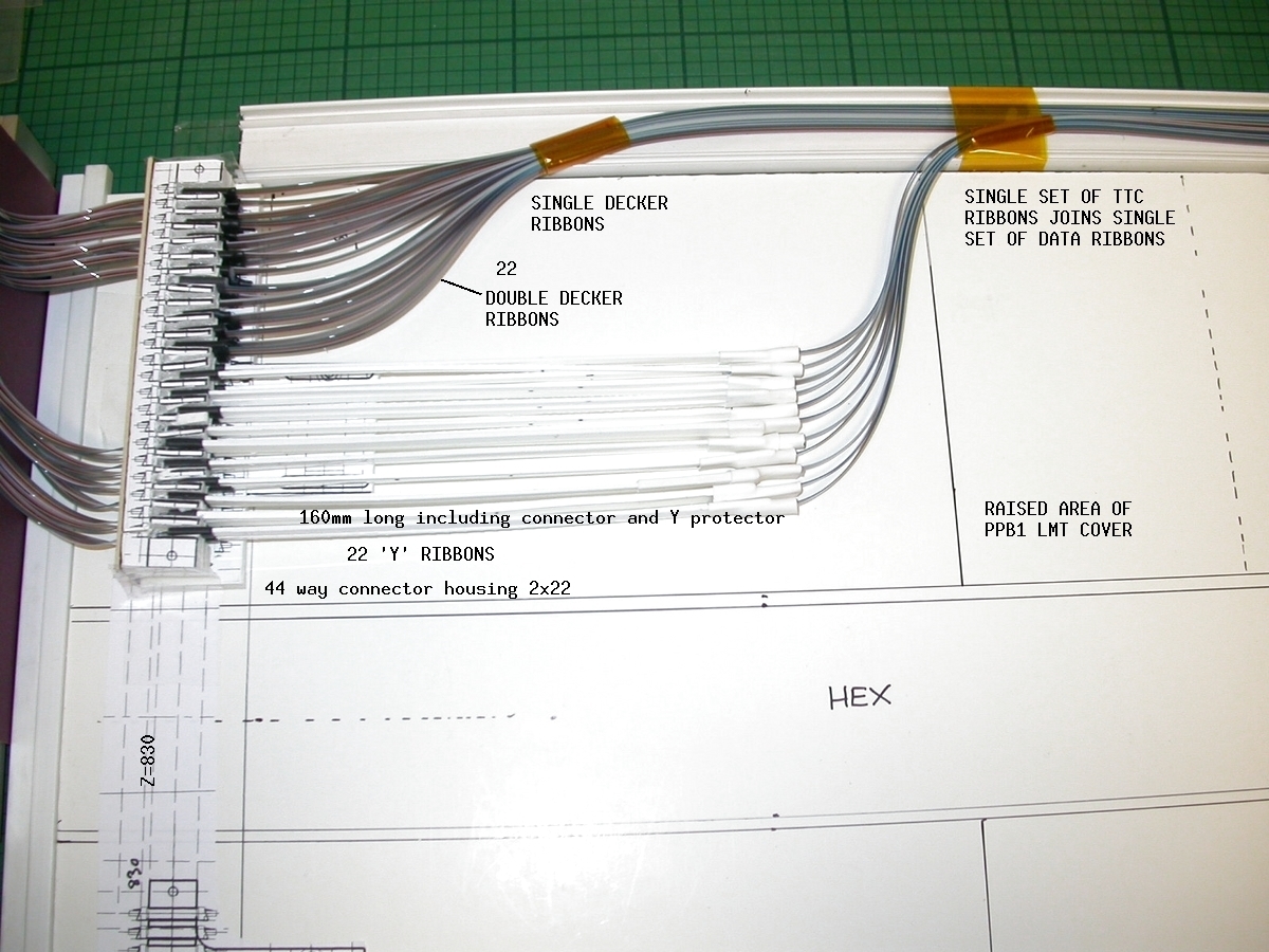
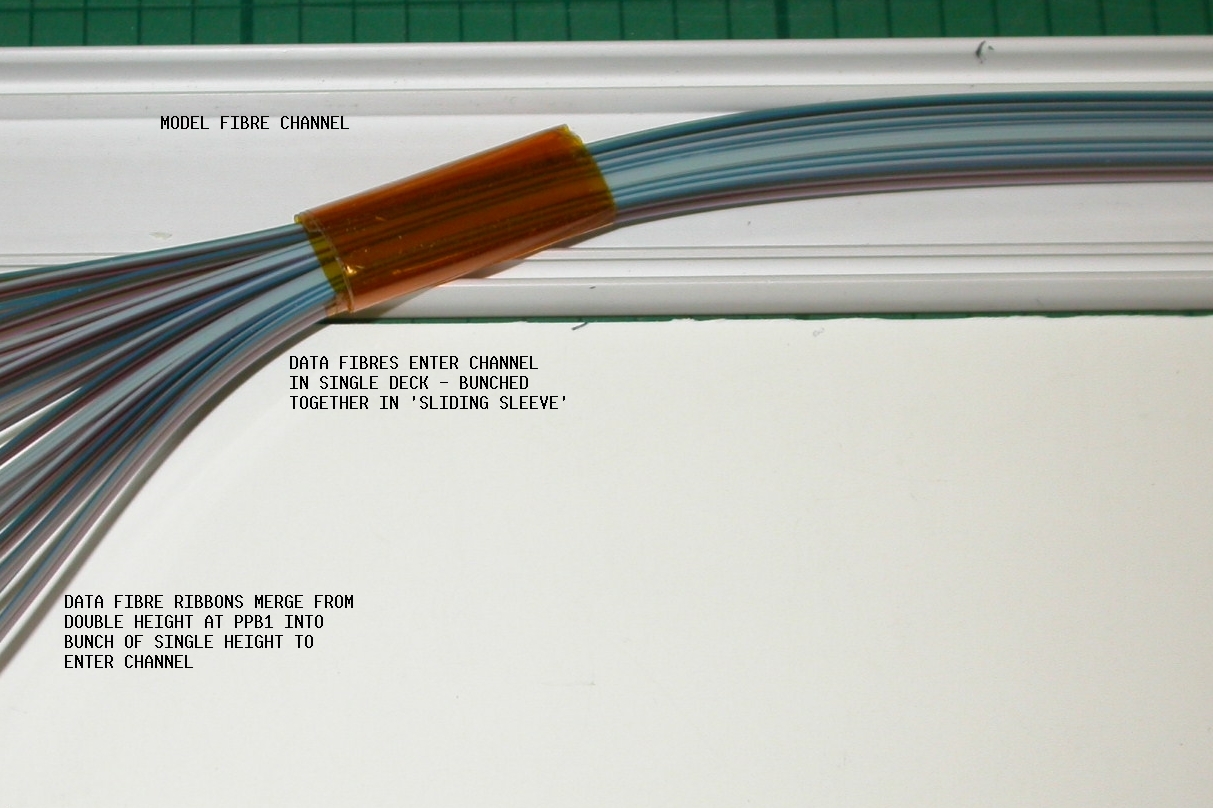
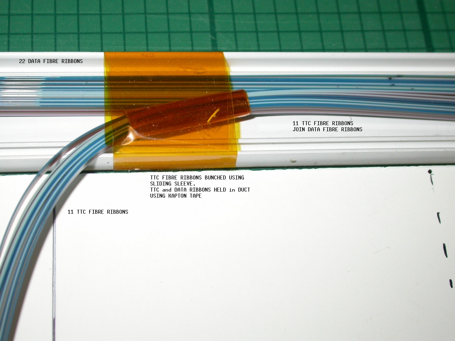
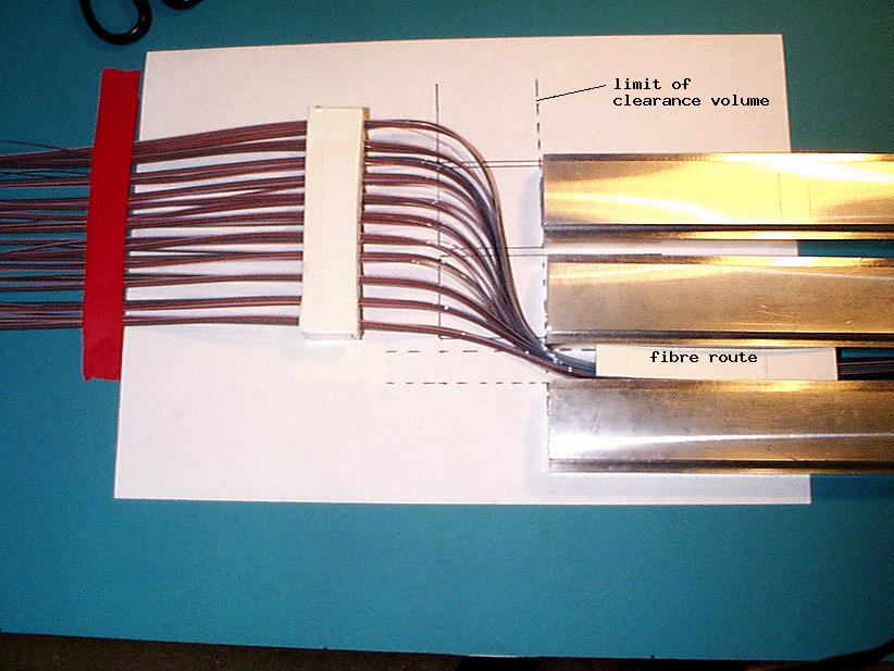
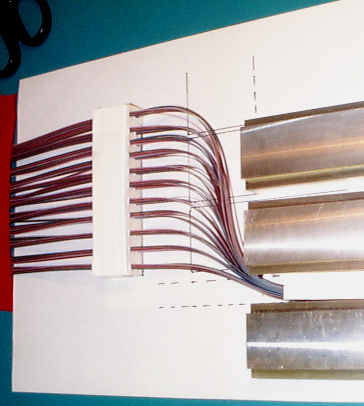
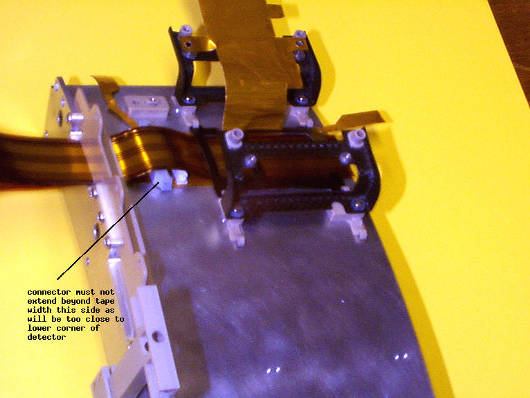
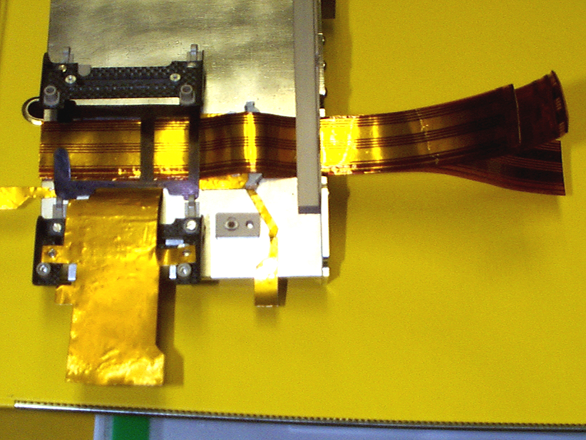
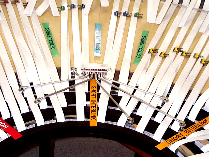
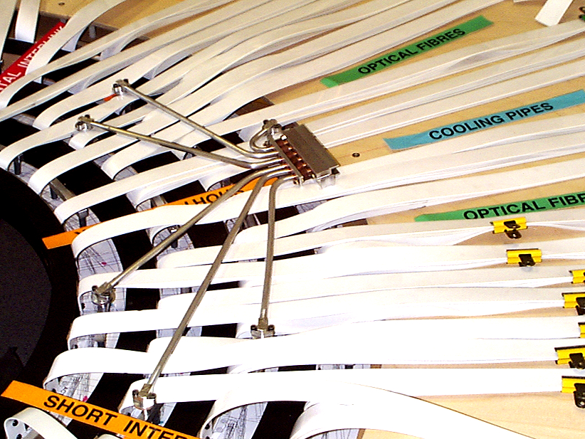
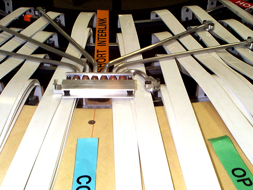
Fibre Routing at PPB1
There was found to be a severe limit on the clearance volume in the region where fibres leave the PPB1 connector area and enter the ducting on the cryostat wall.
The fibre MT connector block is modelled here
Optical fibre is in ribbon form after each splice (seen here on the left) and each ribbon (part of the barrel harness, 250mm long) is connected to long fibre ribbon which exits through ducting by means of MT12 connectors at PPB1. These connectors fit together to form a single block called Fibre PPB1. There is one for each octant.
Here is another view of the model connector block
Here is a view of the trial routing the fibre ribbons from the connector block, keeping them within the limit of the clearance volume, to the channel which will form the ducting between other services.
Another view of the same trial
04.12.2002
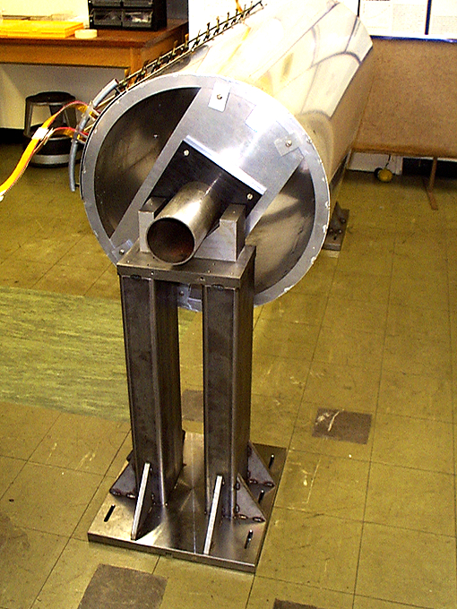
The first design of the Barrel 6 Support Bearing (Geneva, G.Barbier) was machined at UCL out of Al tooling plate. The final bearing will be carbon fibre.
Here are some views of the machined bearing
Here is the .ppt file with notes on trials made with the bearing on the models
and photos of the bearing trials:
Here we can see the bearing on the barrel 6 flange. Note that, with the tapes moved it can be seen that the bearing clashes with the rectangular white tube which represents the end-barrel alignment light path protection tube.
A view of the bearing on the B6 flange showing the gap between the flange and the Thermal Enclosure Bulkhead Note that the four recesses for the low mass tape harnesses need to be enlarged so that the tapes can exit straight off the barrel surface without 'pinching'. The recess edges should not be sharp. Adequate clamping of the tapes is needed here.
A view of the bearing on the surface of barrel 6 showing the gap between the surface and the Thermal Enclosure Bulkhead from the inside.
Fibre routing trials on the bearing:
A view from the barrel side of the bearing showing
fibres from four harnesses routed along th bearing. Note that small clips similar to those used for the fibres on the barrel end clamps will be needed to keep fibres in place on the bearing.
Another view of the fibre routing
A view from outside the barrel showing the fibre routing through the Thermal Enclosure Bulkhead
20.11.2002
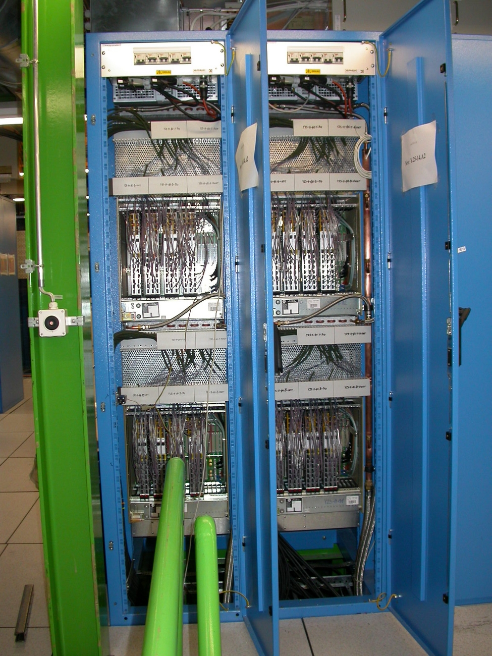
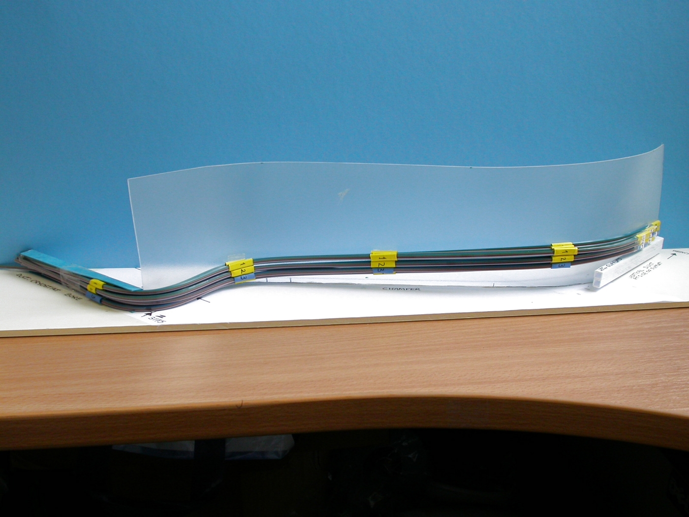
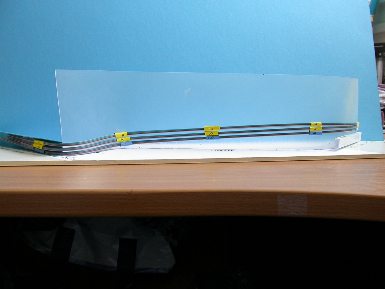
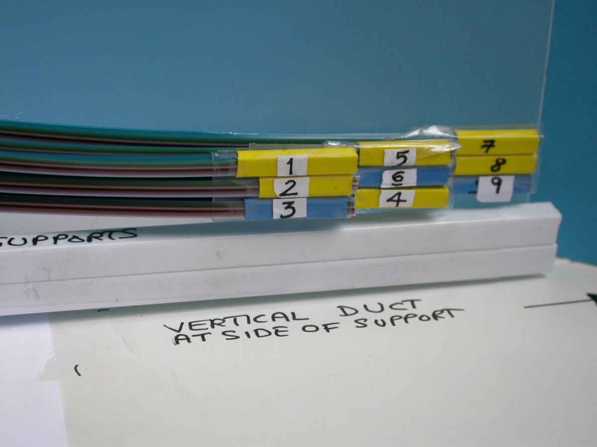
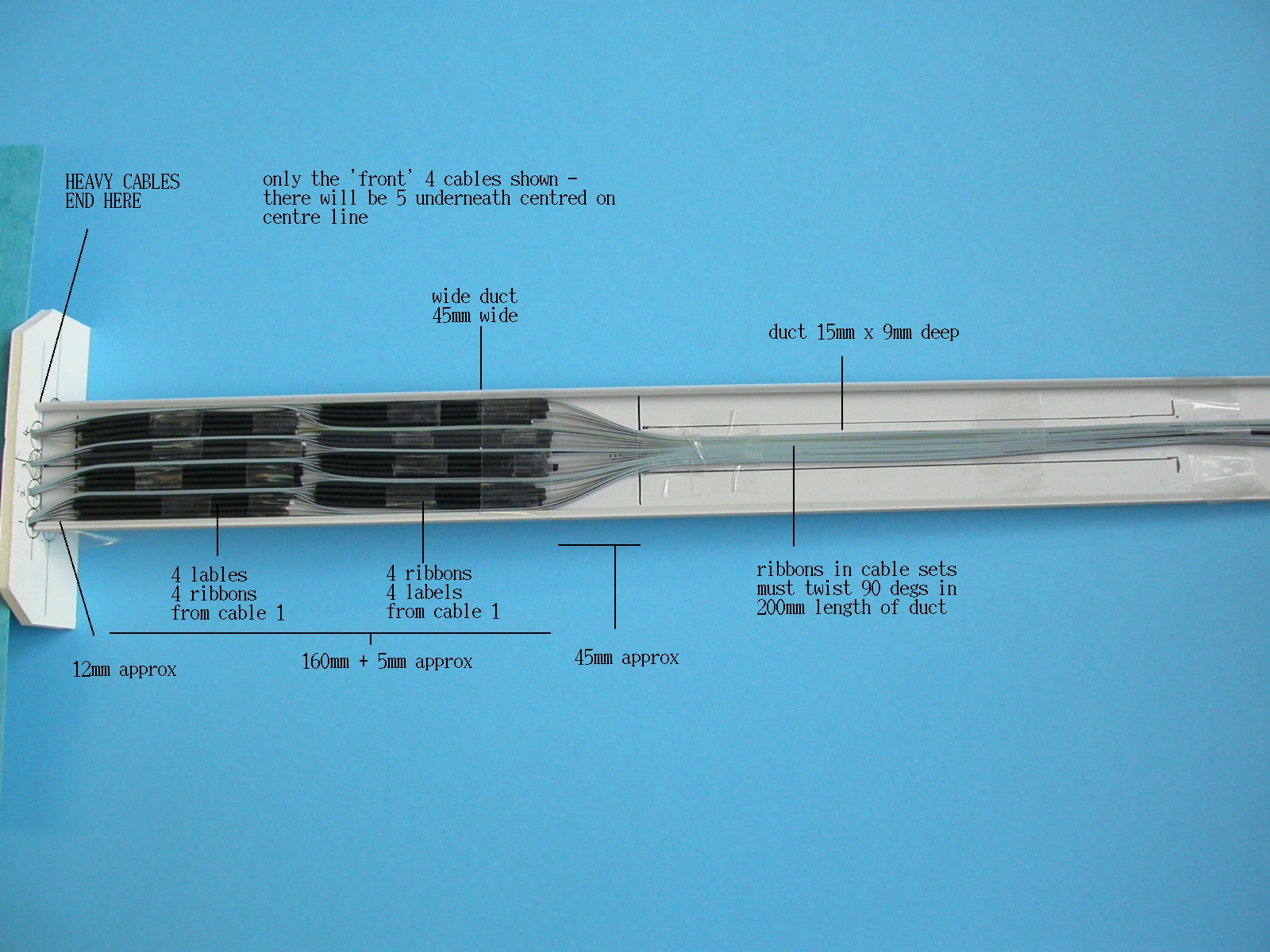
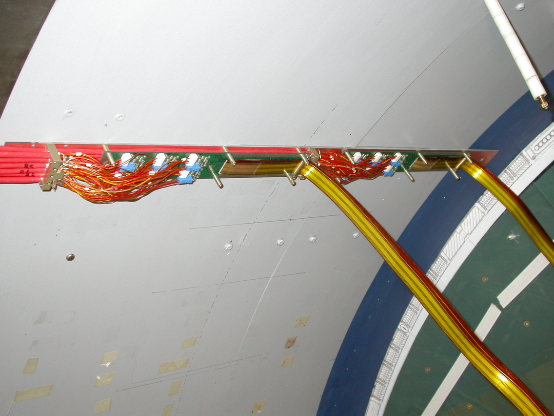
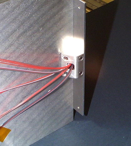
PPB1s with type II cables on cryostat wall
Two PPB1 boards with cables connected up are positioned on the cryostat wall. We found that the long support board would need a profiled bonded surface in order to adhere permanently to the inner radius of the cryostat wall as the whole structure is heavy. The low mass tapes will need strain relief before the right-angle bend onto the cryostat.
05.11.2002
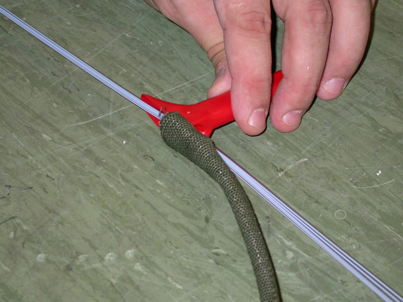
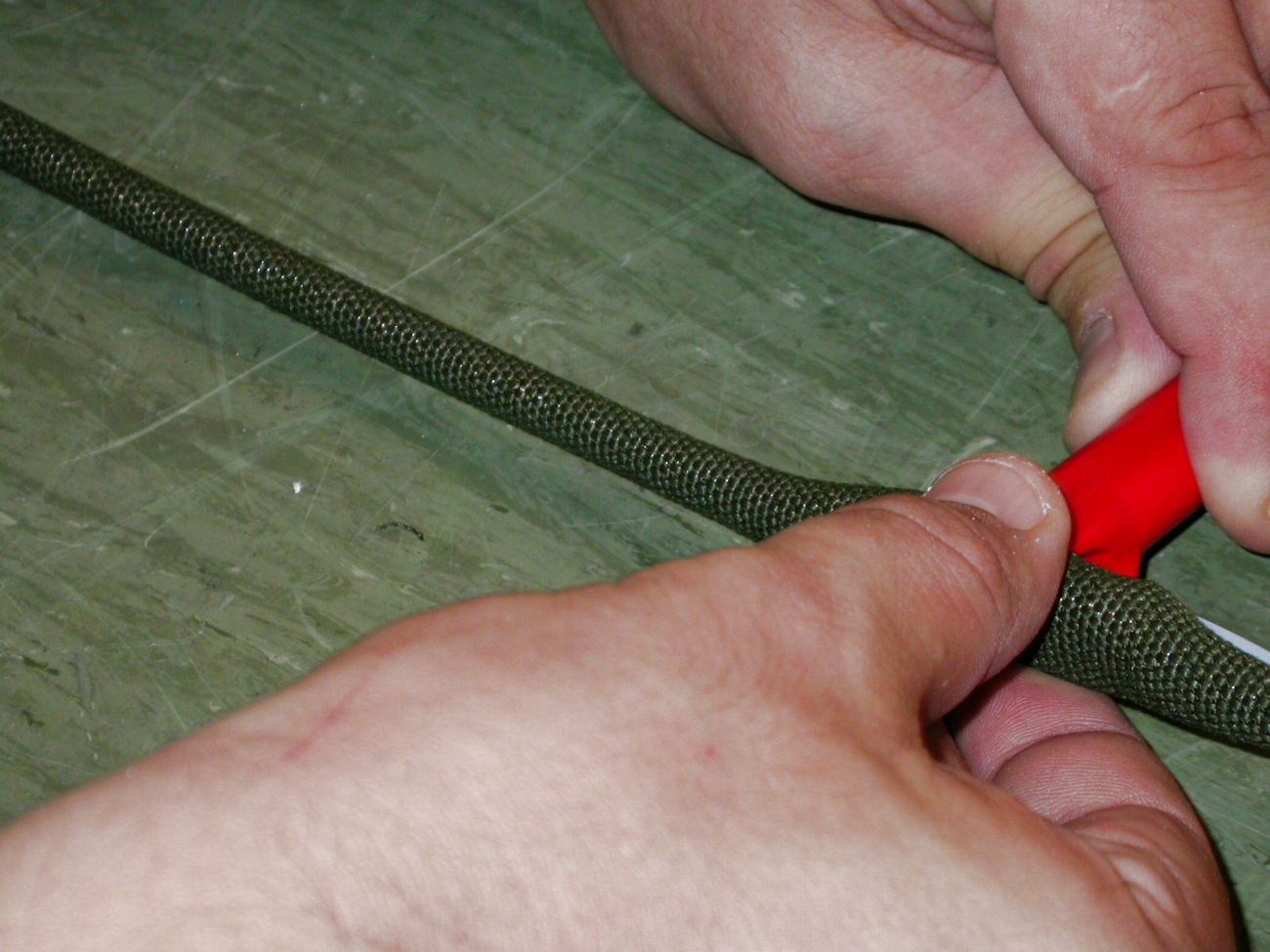
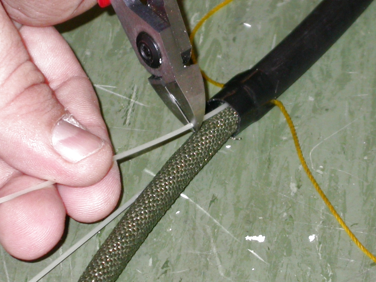
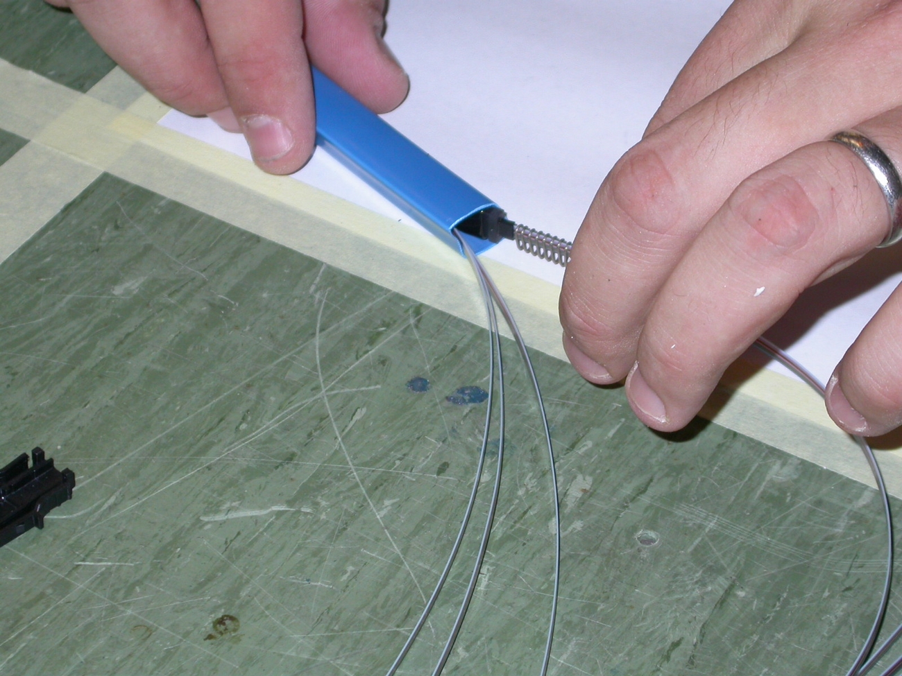
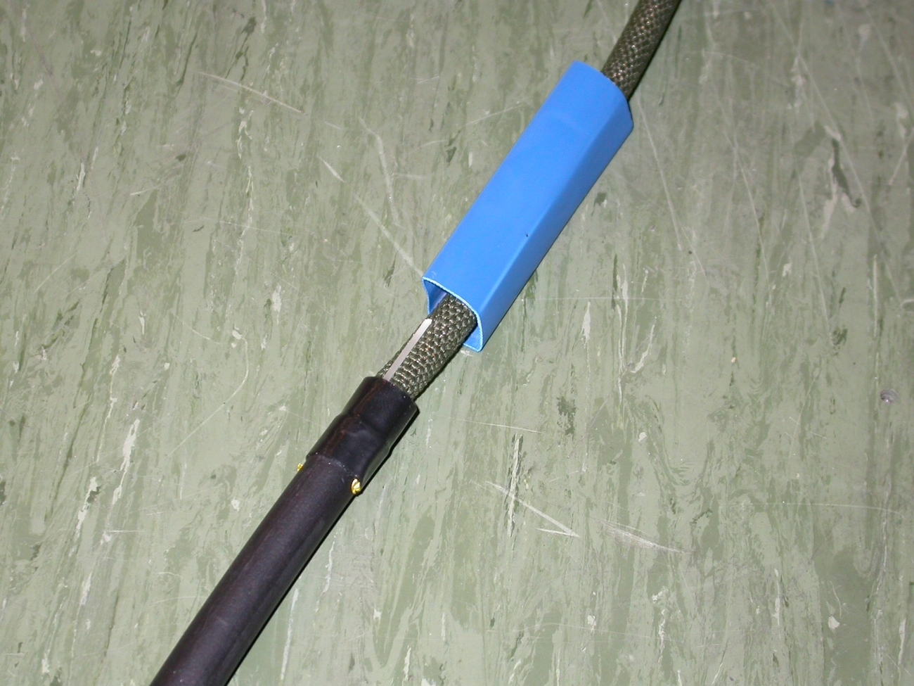
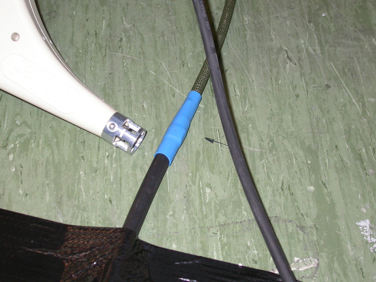
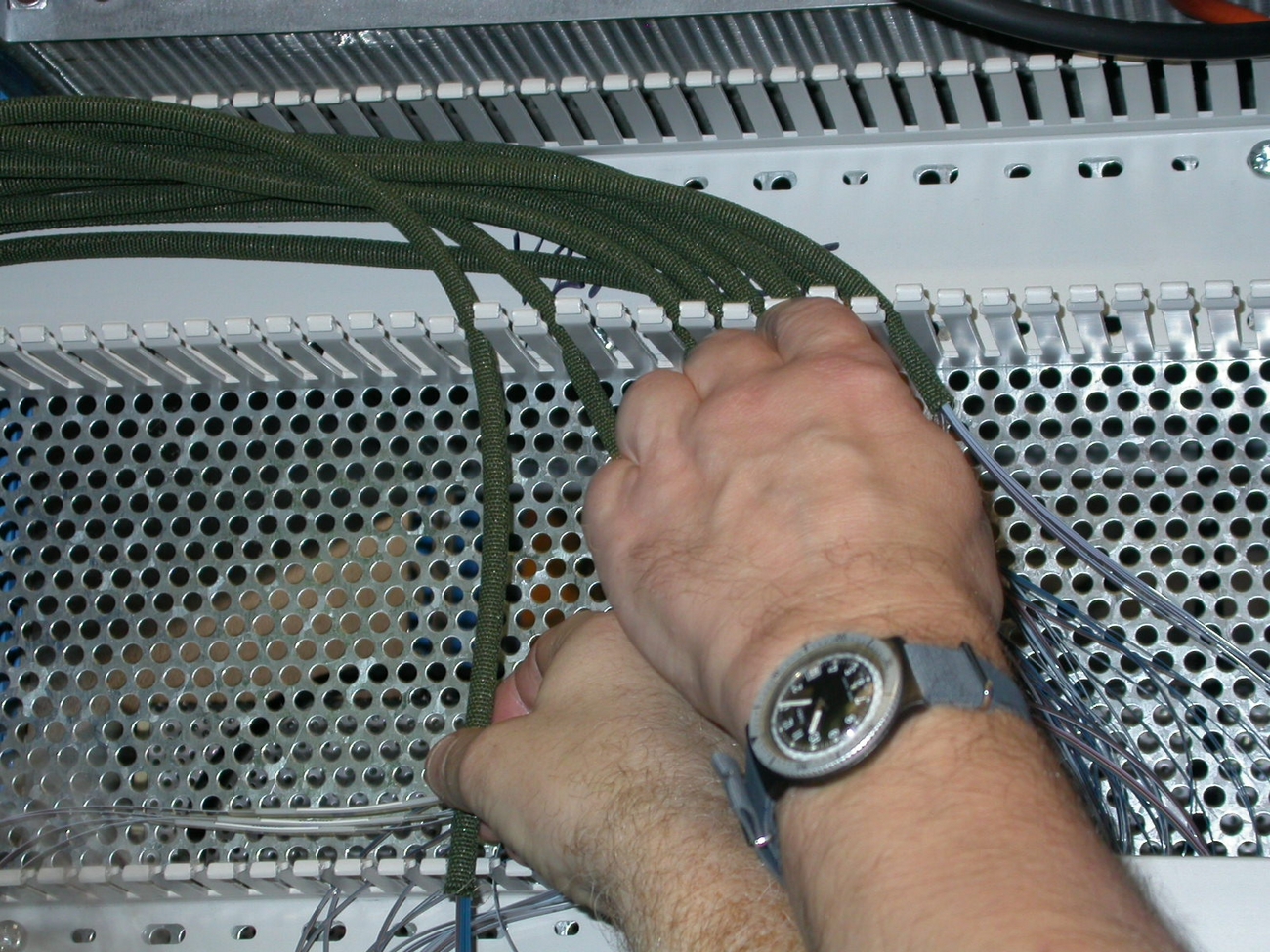
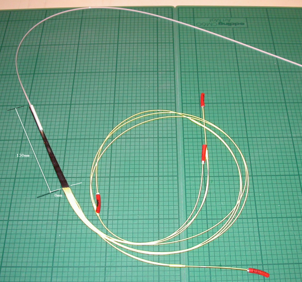
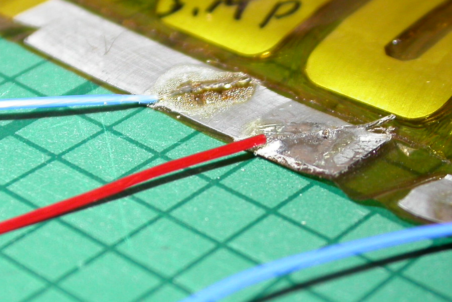
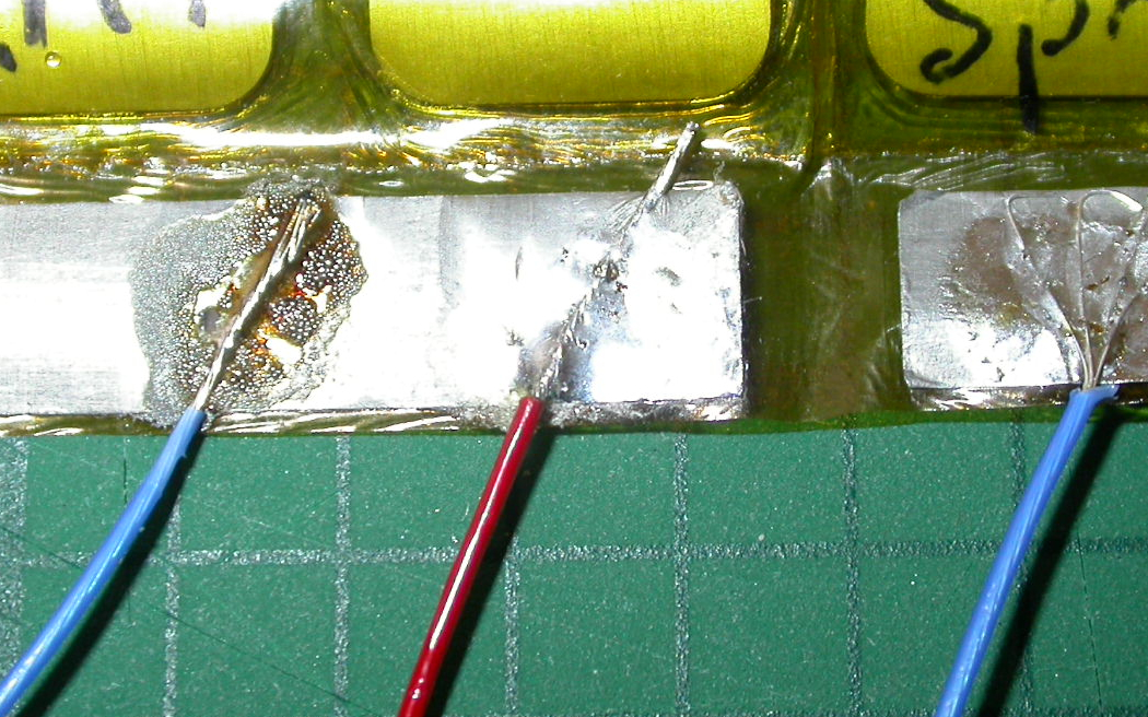
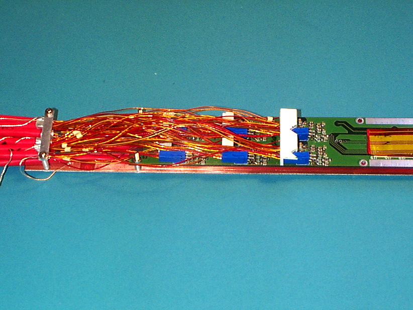
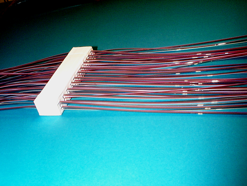
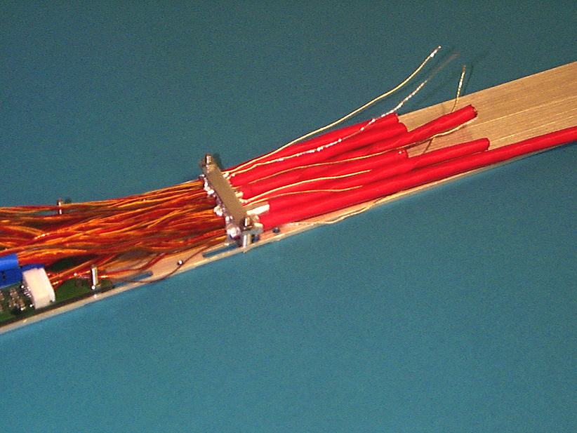
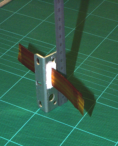
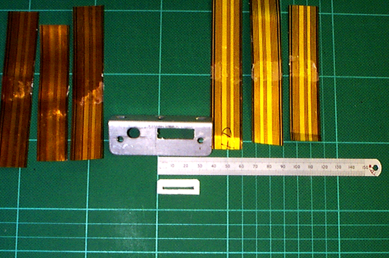
Trials with real PPB1 connectors and real TYPE II cabling
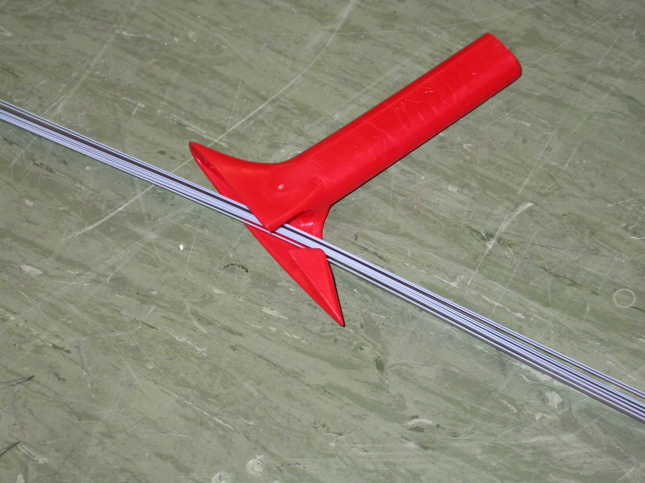
Type II cable ends were stripped and ferrules fitted.An attenpt was made to fit the cables with ferrules onto a PPB1 board. It can be seen that there is not enough space in the clamp (strain-relief) region for a row of 6 cables fitted with strong ferrules.
The 6 cables without ferrules fit in the space
Here is a sketch of 'ferrule clamp' - a possible solution to making a secure clamp for the Type II cables?
This shows stripped Type II cables clamped - the straight bar provides inadequate clamping force
A view showing the length of stripped cable needed to enable connecting We noticed that the individual cables make a VERY stiff bunch, the power cables being extremely stiff.
Another view showing stiffness of cableswith one JST (white) and one FCI power connector (blue) connected up on a real PPB1 board.
11.10.2002
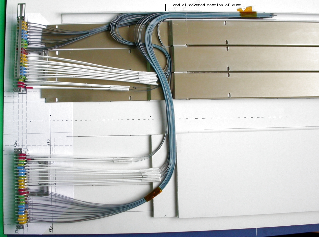
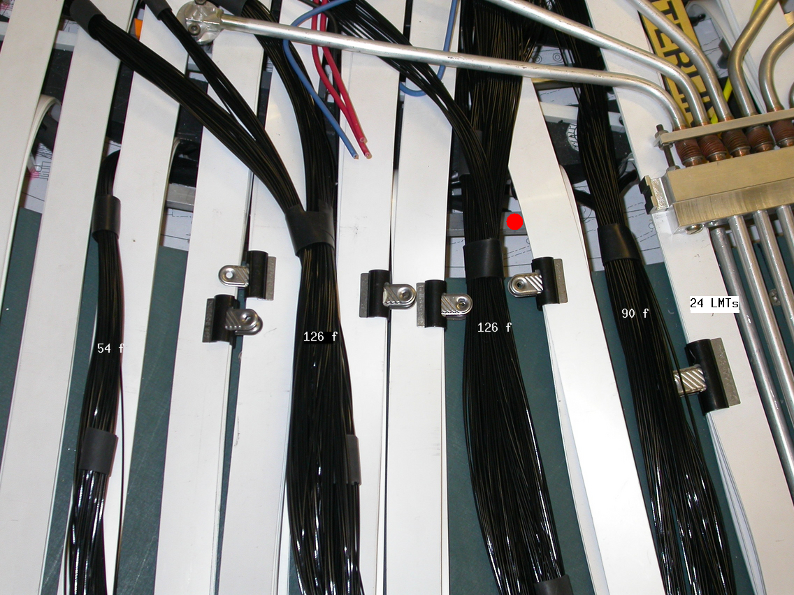
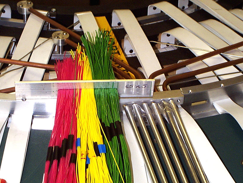
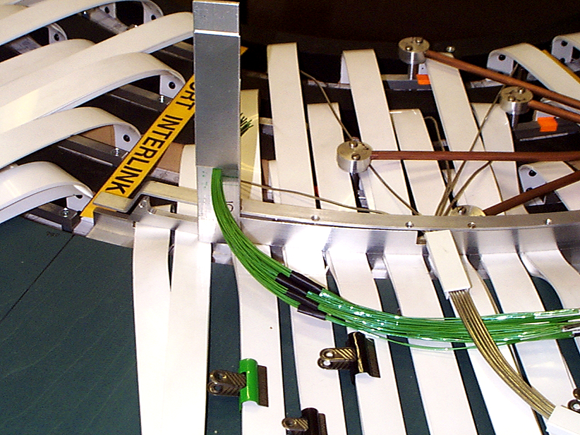
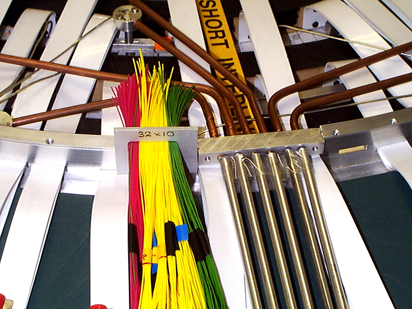
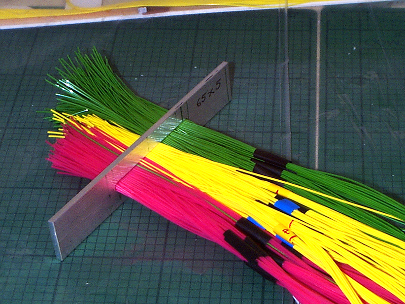
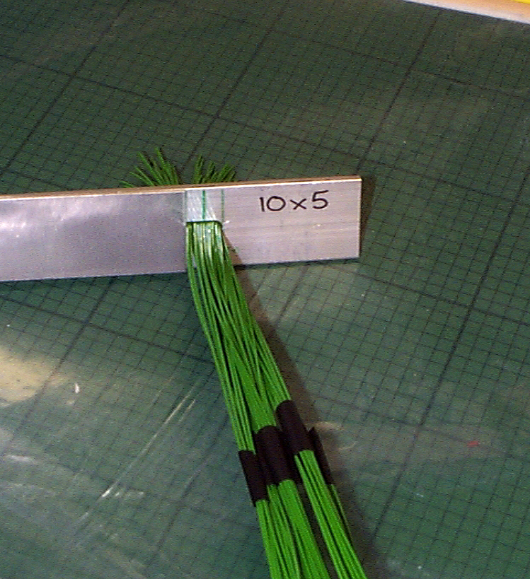
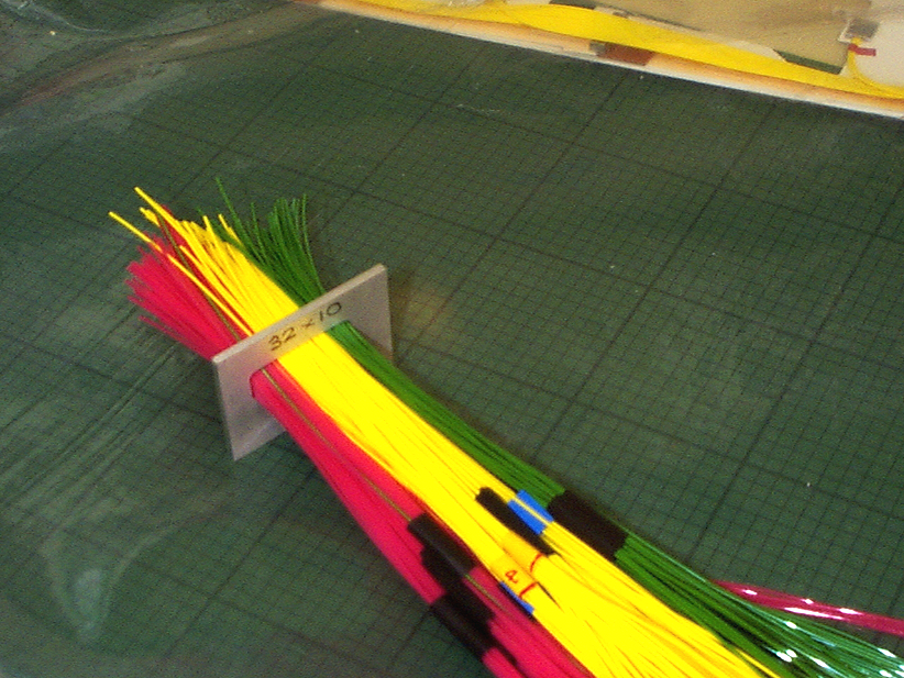
Fibre routing through the Thermal Enclosure Bulkhead - assessment of size of apertures required for fibres from one octant only
The .ppt file with diagrams of the fibre numbers and routing for one octant of one barrel end can be found here
Shown here is a fibre bundle in a 65 x 5mm slot placed above the approximate region in the TE bulkhead where it would be located.
There are 342 sleeved fibres in this bunch, from one octant of all four barrels.
The remaining 54 fibres (part of the set from barrel 6 go through an Auxilliary slot) further along the bulkhead - and curve round to join the main fibre duct.
An alternative slot shape 32 x 10mm for the main bunch of 342 fibres was made.
65 x 5 bunch on bench
10 x 5 Auxilliary bunch on bench
32 x 10 bunch on bench
NOTE that these fibre bunches, like all other services, will have to be sealed in special grommets at the TE to prevent gas /thermal leakage - this means that the slot sizes will have to be larger than shown here.
27.09.2002
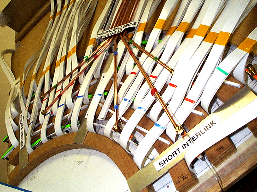
Cooling capillaries - new routing brings the capillaries alonside exhaust pipes (heat exchange proposal)
The capillary routing remains unchanged from the previous version in the region from the barrel ends and through 4 exists per end through the thermal enclosure bulkhead.
Outside the thermal enclosure, the capillary route changes, with the capillaries bending round to join the exhaust pipes
which serve the same barrel cooling units. Note that the exhaust pipes have connections at the barrel end and the thermal enclosure bulkhead and again beyond the right-angle bend in the PPB1 region - BUT the cooling capillaries are continuous without connections until the PPB1 region.
A close-up view of the region where capillaries meet
exhaust pipes showing a possible layout.
27.09.2002
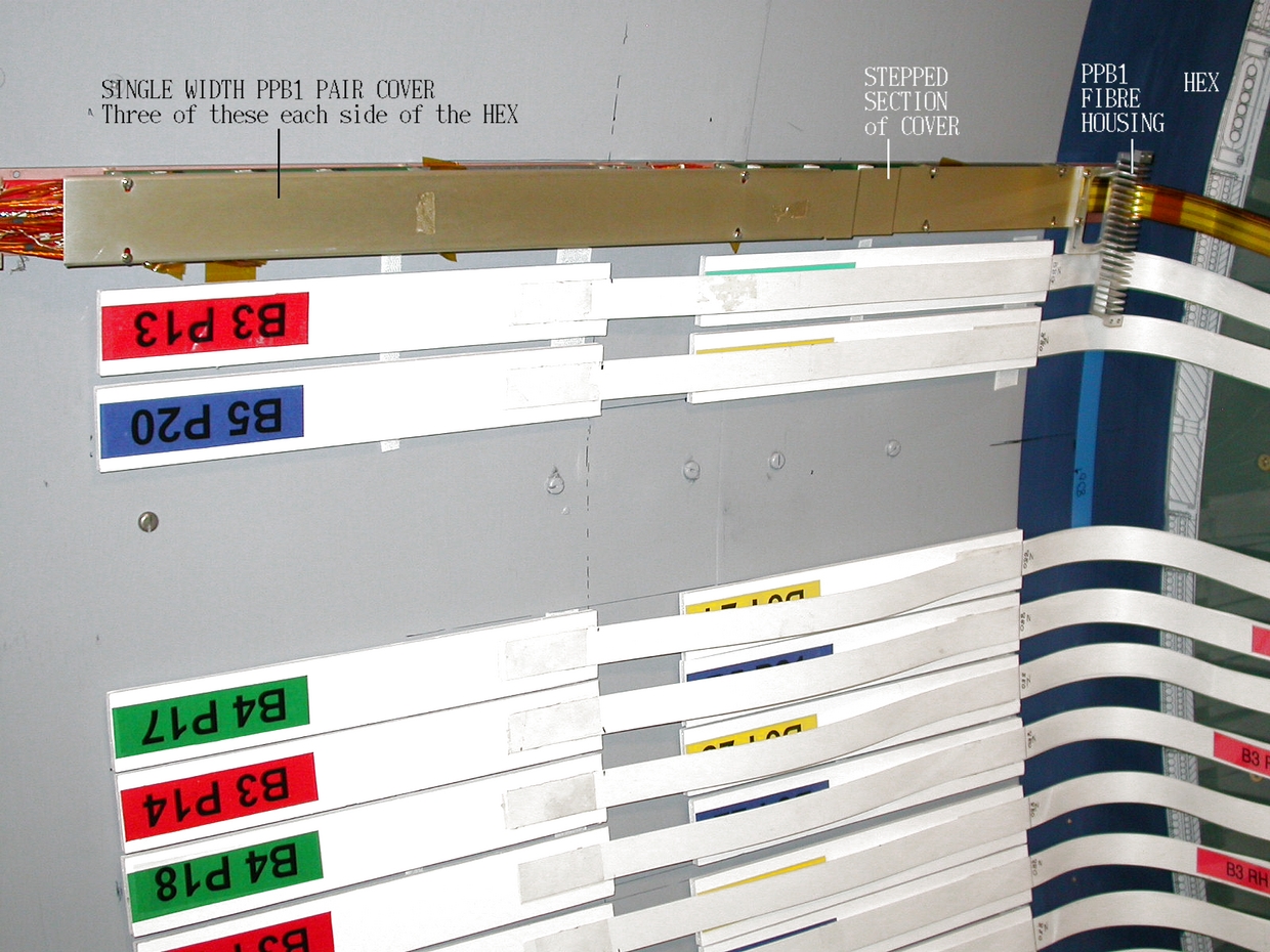
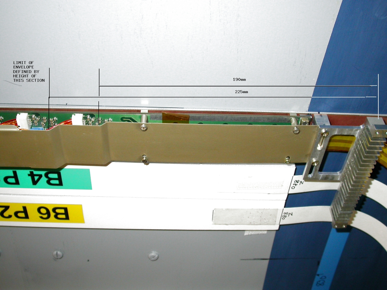
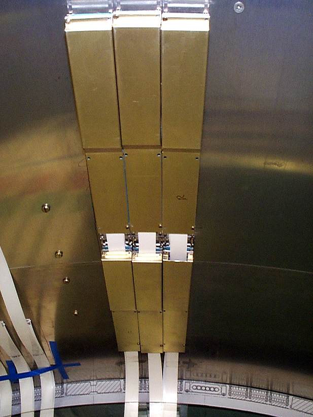
Trials with separate PPB1 covers on the model cryostat
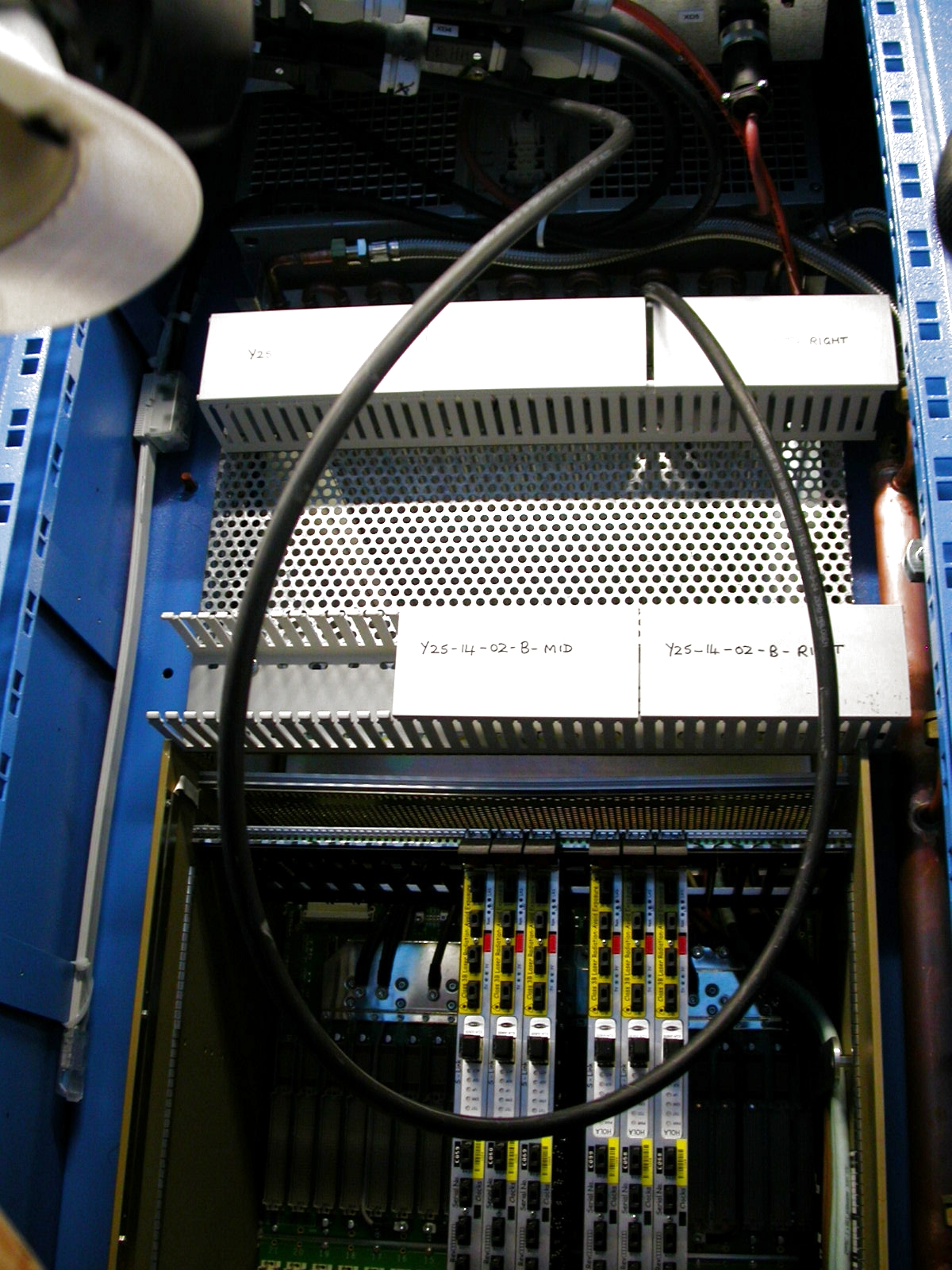
A view of a set of 6 PPB1 boards (3 pairs) with separate covers on support boards fixed to the model cryostat. the covers screw onto the PPB1 boards and the PPB1 boards are stuck to the cryostat wall.
Another view of the set of 6 FRONT and REAR PPB1s with covers on the cryostat
25.09.2002
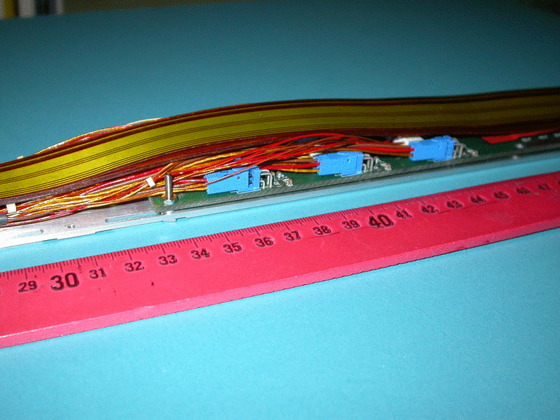
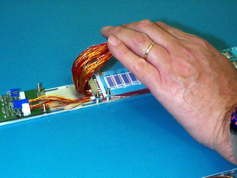
First trials using Type II cables on model PPB1 boards fixed to the support board.
6 Real Type II cables were fixed to a model PPB1 board screwed onto a model support board. This shows the FRONT board which goes onto the support board first
Here is a close-up of the modelled connector area on the front PPB1 board.
The REAR board with LMTs passing OVER the FRONT board.
This shows trials with the first design for covers for the PPB1 boards. Each board has a separate cover.
A view showing the construction of the covers
30.08.2002
New model harnesses have been made.
An annotated photo of a LH harness showing the new version of the fibre routing requested by Taiwan in order to separate the TTC fibres into a separate set along the harness length.
A close-up of the LH dogleg showing the TTC fibre on the right of the 3 - routed up to the separate set of fibres. A permanent harness clip is shown here.
Close-up of harness with TEMPORARY clip and with fibres on kapton adhesive tape.
09.08.2002
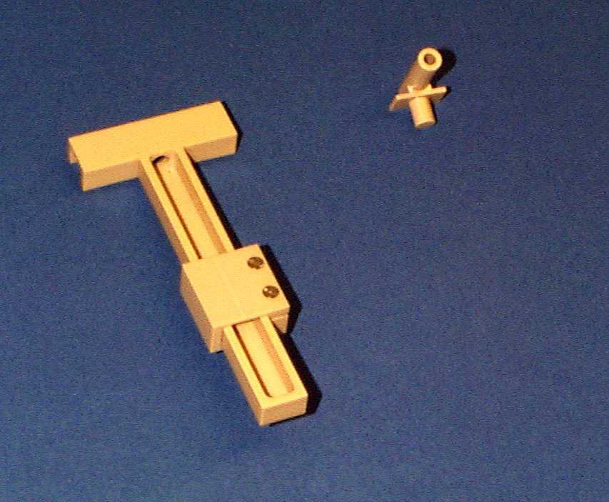
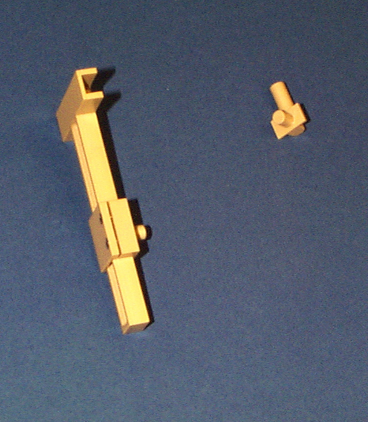
The first design of the 'tandem' PPB1 full-length support plate allowsfor a few mm sliding adjustment.
Here is a full length view of the back of the support plate.
A close-up view of the sliding section between fron and rear boards
A view of the model octant with low mass tapes arranged on the cryostat with front and rear sets spaced as for sliding plate
All parts required for the PPB1 sliding support plate on the bench
22.07.2002
Dimensions in Z of dogleg to interface PCB to LMT end for LH and RH doglegs have been measured
Here is a drawing of LH and RH doglegs with interface PCB, LMT end and tall parts of the dogleg to LMT connector shown.
Note that the main dimensions are with reference to the BRACKET CENTRE line. (Dimensions in grey are wrt dogleg centre line as on the original dogleg drawing by Mark Jones).
The highest parts of the connector are shown.
These measurements were made in order to get an accurate distance of the LMT end from the MODULE PHYSICS CENTRE as the these positions are used to define the
tape lengths on the barrel.
An updated list of LMT lengths is now being made.
10.07.2002
Routing of cables from temperature sensors and other sensors (DCS)
Sensors on the barrel will have cables running from barrels over LMTs at the barrel ends, through the thermal enclosure bulkhead and out to PCB connectors. Here is a very preliminary layout for the DCS cable routing from cooling pipe temperature sensors.
27.06.2002
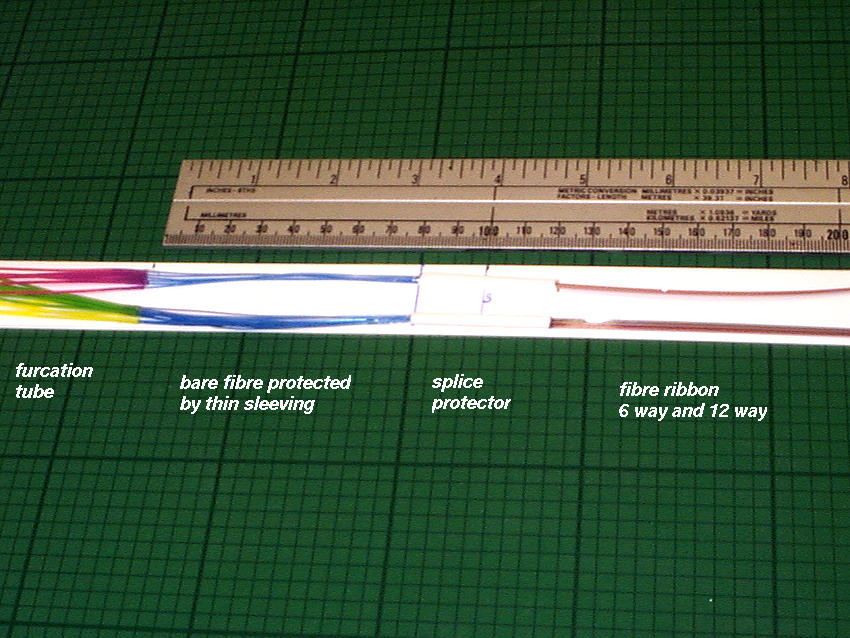
Taiwan - latest dimensions of the readout fibre splice protector and furcation tubing
Here is a drawing (not to scale) of the Taiwan splice protector sample with the transition from fibre sleeved in furcation tubing to bare fibre to splice inside the splice protector to ribbonised fibre . The whole length is protected by heatshrink tubing 'SUMITUBE 125deg C OFT F diameter 5.0 VW 1 SUMI-PAC CSA HS X'
Note that the yellow and other coloured furcation tubing used was found to allow light leaks so the decision was made to use black furcation tubing - however Taiwan notice that the inside and outside diameters are greater than the coloured tube diameters. (O.D. for yellow tubing was 0.9mm).
The multicoloured sleeving on the ribbonised fibre must now be covered where it comes close to the module detectors. This length will be included in the revised table of fibre lengths requested by Taiwan to allow for a 2nd repair between splice and dogleg (table of lengths previously allowed for one repair only).
18.06.2002
Valencia SCT Week report on status of model work and end of meetings update
Status report page 1
Status report page 2
09.06.2002
Complete barrel 3 model harnesses
Here is a photo of two complete barrel harnesses (LH and RH) to the latest dimensions with latest fibre layout and length, with spliced sections and latest dimension model LMT boards.
Here is a close up of a section of the harness showing temporary harness clips made of moulded plastic (Oxford).
07.06.2002
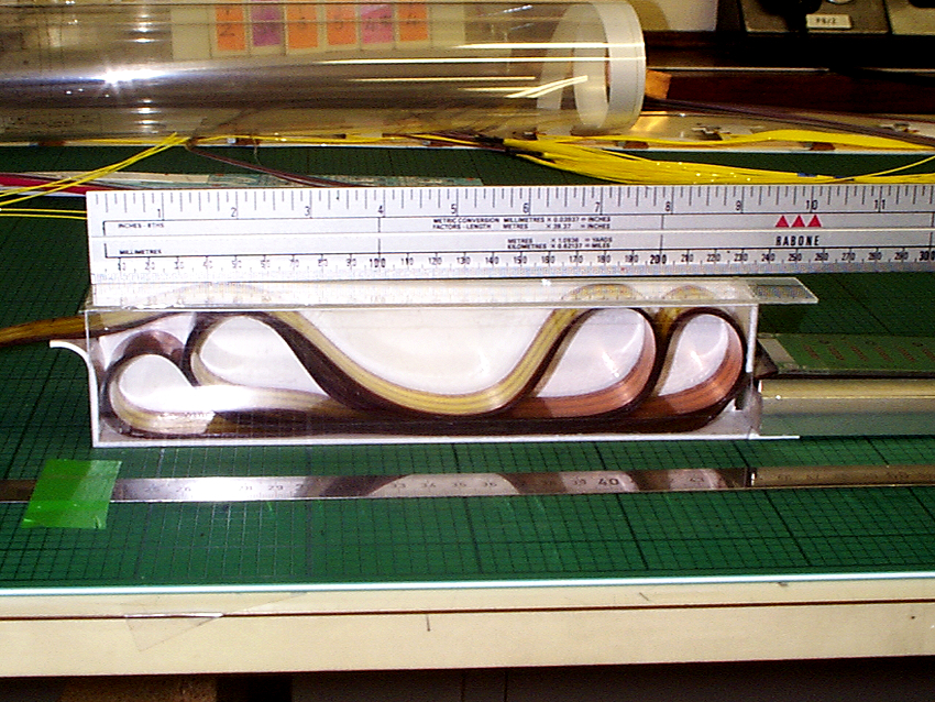
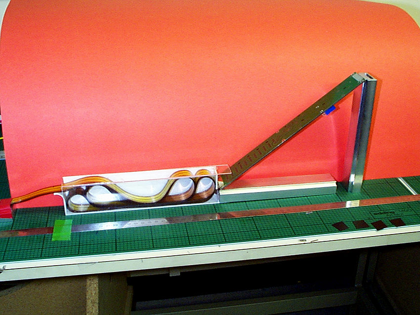
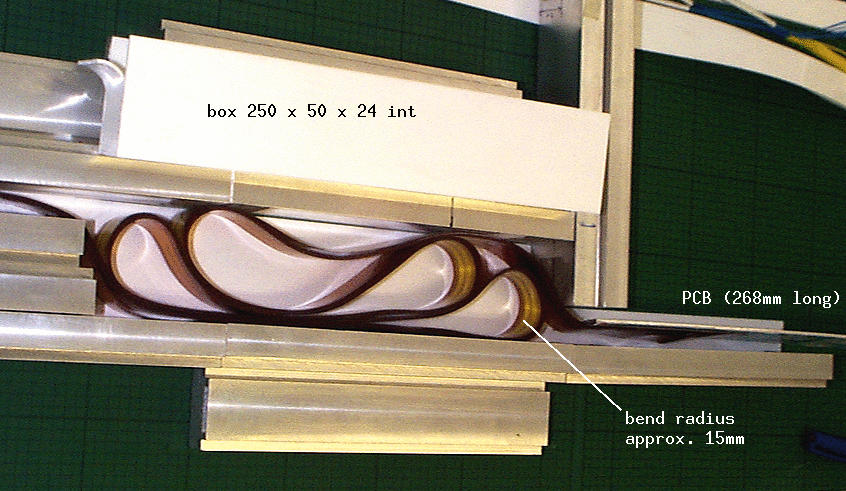
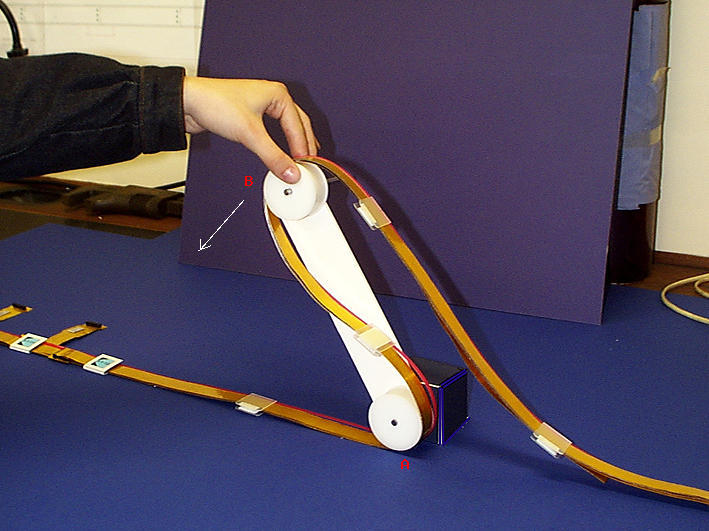
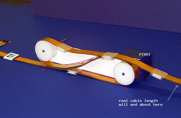
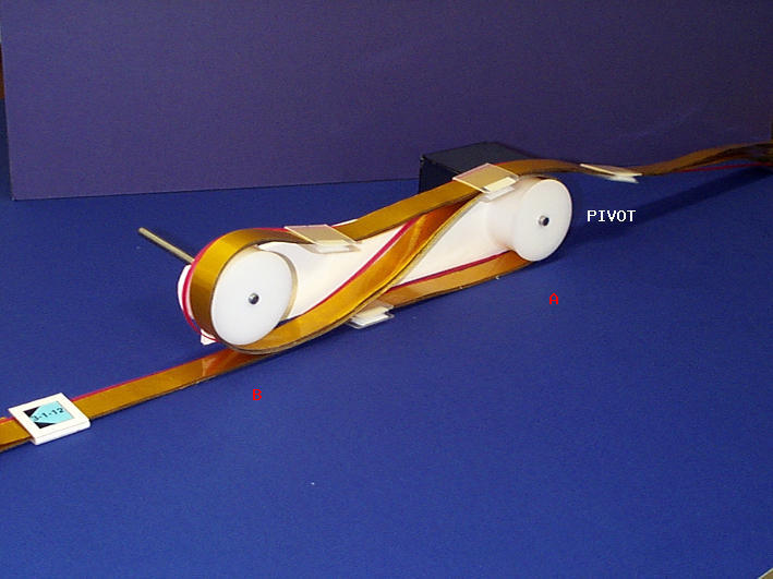
Services cage - trials with 230mm long LMT box
An additional outer support ring is necessary at each end of the barrel, at the
edge of the services support extensions. This means that the length of the boxes housing the services has to be reduced from 250mm to 230mms. Trials were done to determine if it was possible to accommodate a barrel 3 harness (the longest) in a box 230mm long.
Here is a view of a box 230mm long with real, correct thickness tapes (B3 harness length) folded, terminating on the connector board immediately outside the box on the right.
NOTE that the minimum radius of the tapes is now 13mm.
Here is another view of the box with the connector board lifted at an angle for type 2 cable connections to be made on the underside.
07.06.2001
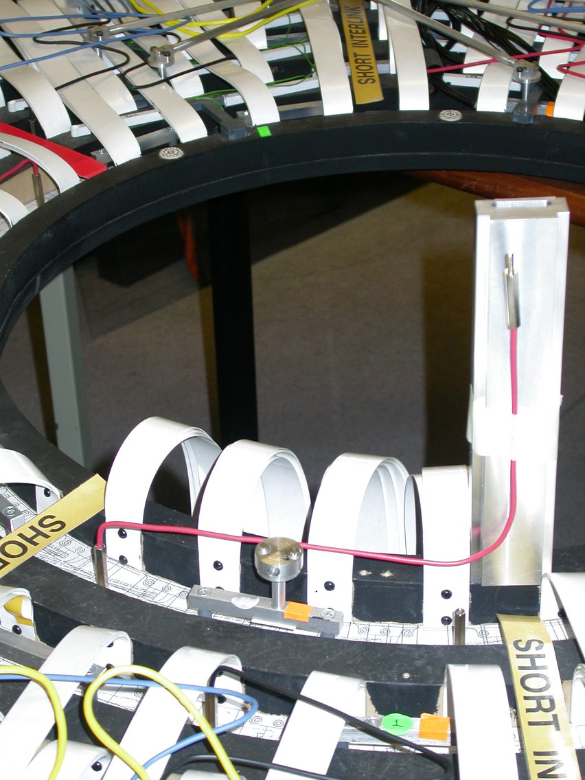
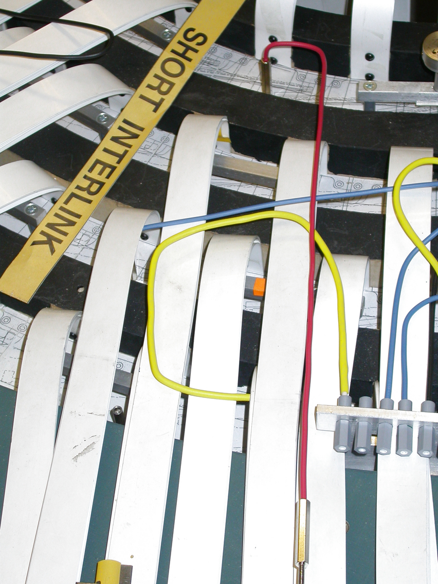
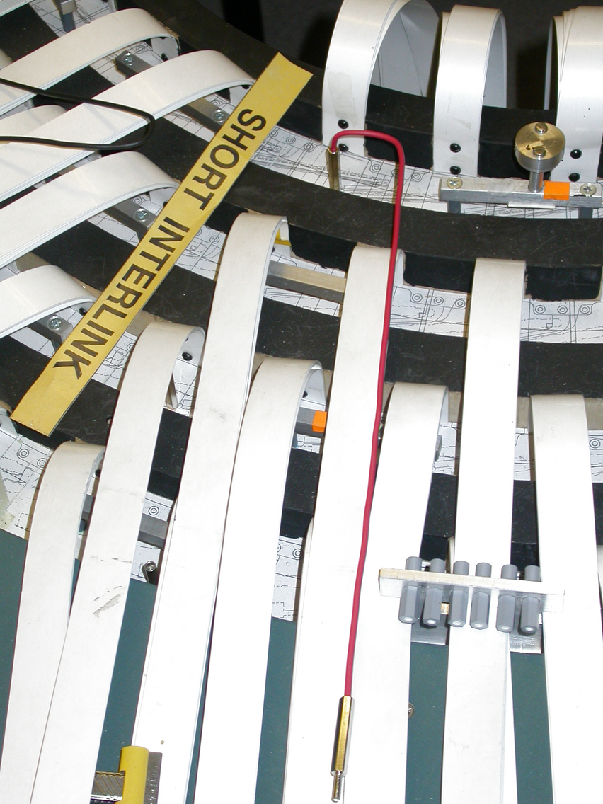
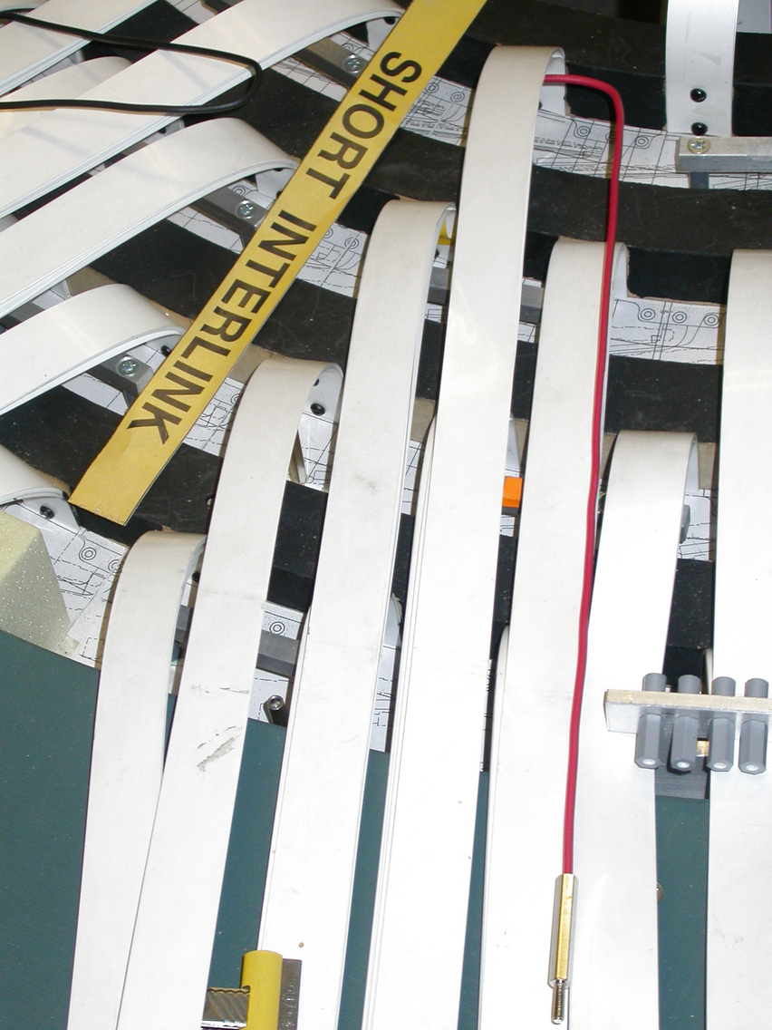
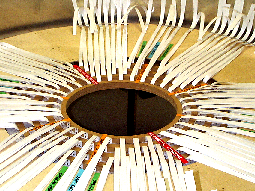
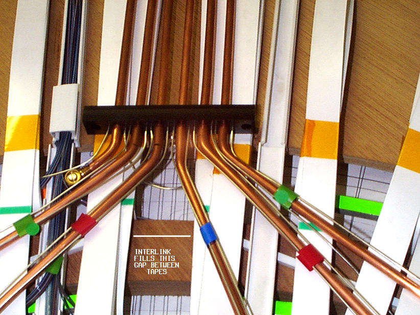
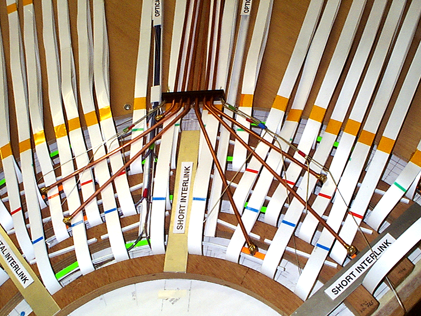
End-Barrel 3 model sector with harness interlink
The model -Z end sector with 2 doglegs, fibres for 2 harnesses, the harness interlink which links 2 harnesses and lies under the fibres, together with the folded dogleg redundancy arm. This arm at the harness end is unused as the interlink is connected instead.
10.05.2002
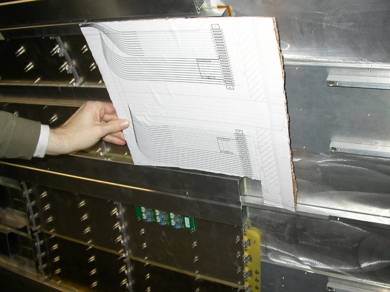
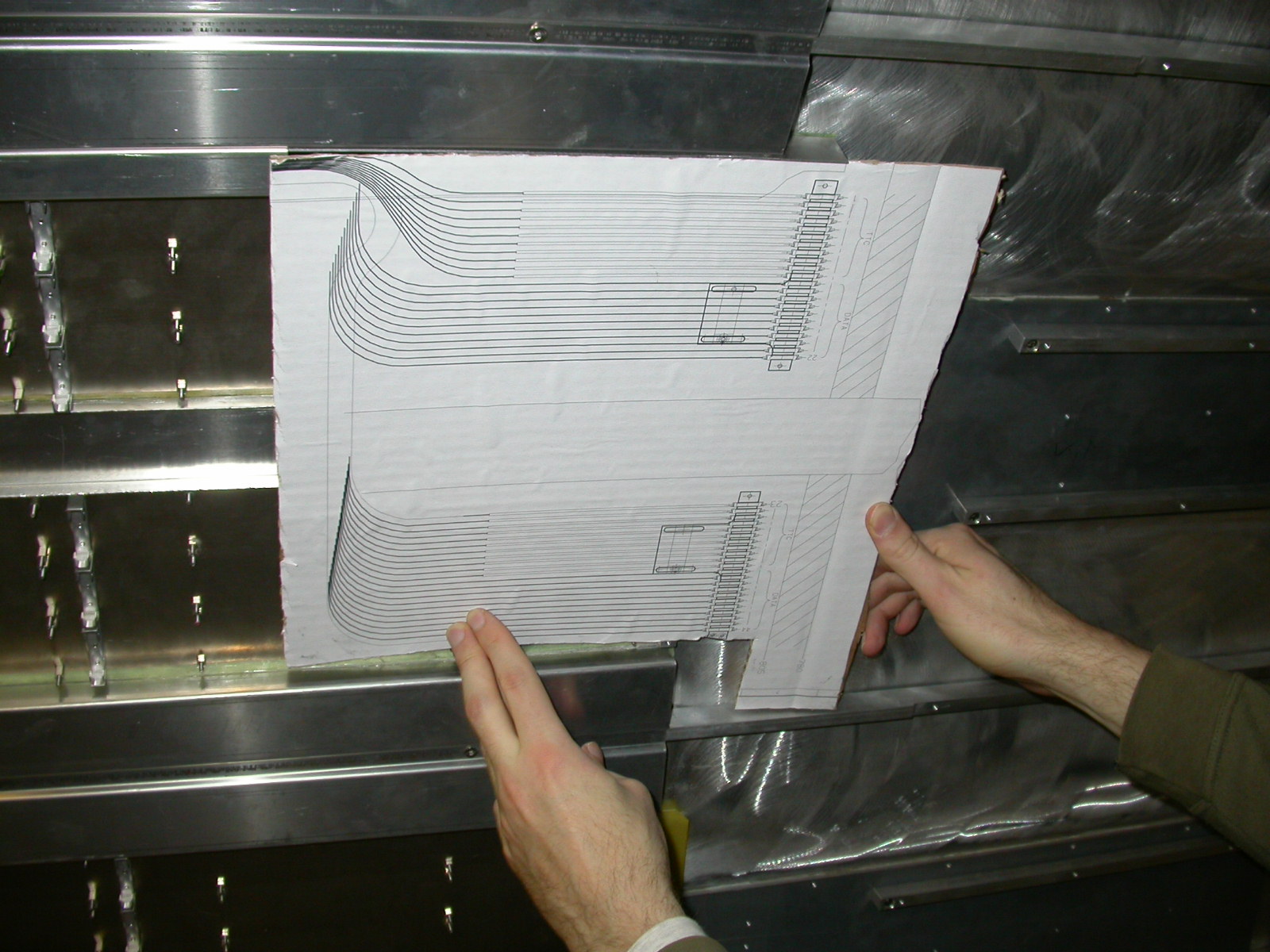
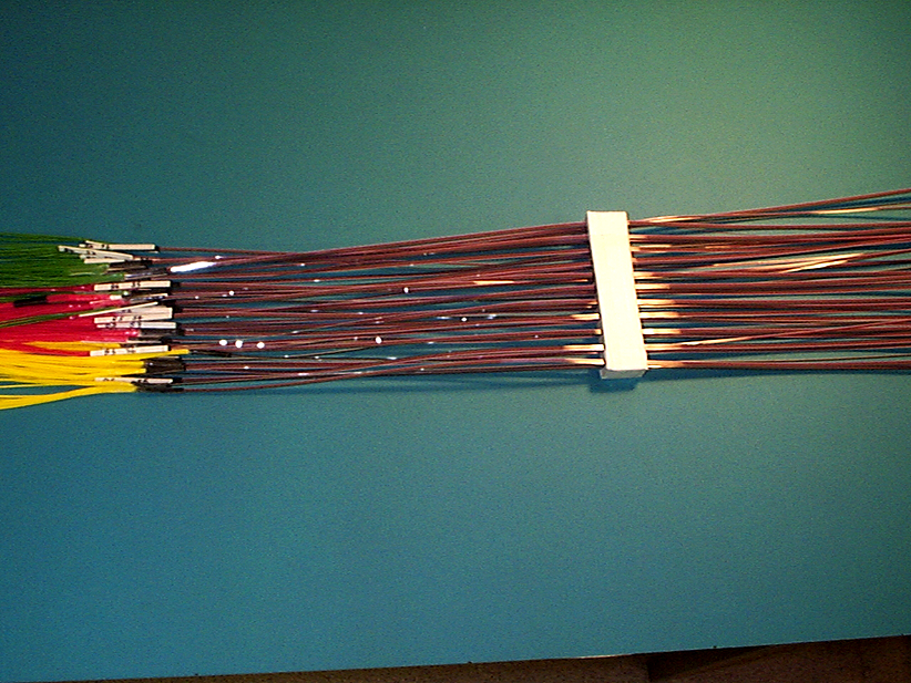
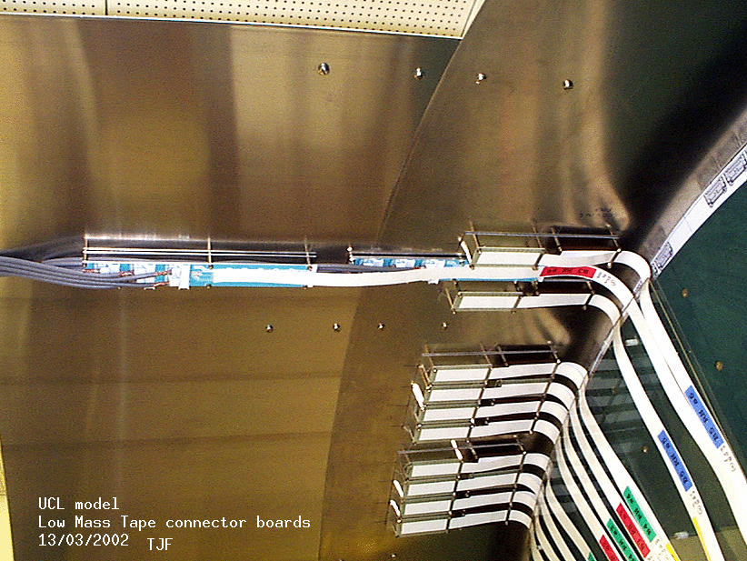
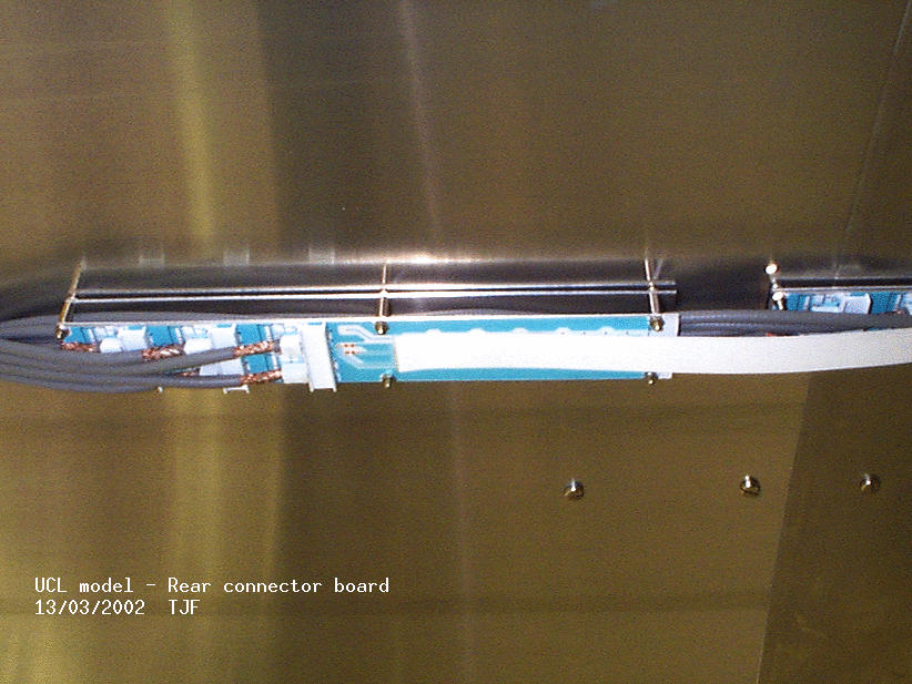
PPB1 region showing the new length model LMT connnector boards with real type 2 cables
Here is a view of the model cryostat wall with the two connector boards. The 6 real type 2 cables are stripped back to allow access for the 6 connectors. The sleeved cables are held togther using strain relief brackets (not shown). Note LMTs going to the rear connector (eg barrel 3) pass over the LMTs, stripped cables and connectors of the front connector board. Type 2 cables from the front connector board (eg barrel 5) go between the plate attached to the cryostast and the rear connector board.
The LMT connector board 268mm long x 38mm wide
10.05.2002
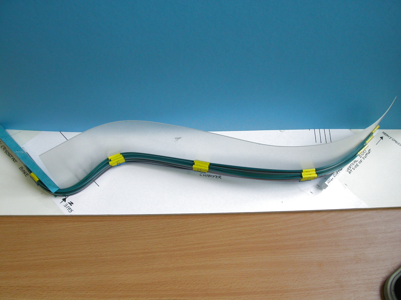
New design of fibre duct (Ian Wilmut RAL)and cooling capillary tube layout
Here is a section on the 360 deg end barrel model showing capillary tube routing up to and beyond the Thermal Enclosure and the layout of the fibre ducting (for readout and alignment fibres) up to the thermal enclosure. Not that this is as it would appear BEFORE the addition of the cooling exhaust pipes which would lie over the other services.
04.04.2002
Lists of items with dimensions to be stored on the B3 services cage
Services which run from the barrel to the patch panels have to be stored on services support extensions at both ends of each barrel, within a limited space envelope. Low mass tapes are stored in enclosures on these extensions (cages)
with optical fibres, DCS wires and cooling capillaries stored in enclosures
between each set of tapes.
Here is a provisional list of items for the services cage at the barrel 3 +Z end
Here is a provisional list of items for the services cage at the barrel3 -Z end
note that the lengths given on these lists are ONLY the lengths in need of storage on the services cages.
Here is a photo of a possible layout of low mass tapes in the enclosure
26.03.2002
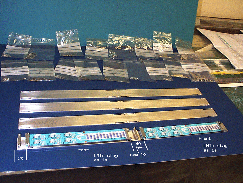
The new long LMT connector board is now 268mm long
Here is an updated dimensioned drawing of the PPB1 area along Z which replaces that of the previous entry to allow for the extra length.
14.03.2002
The new long LMT connector boards for PPB1 have been modelled and assembled on the vertical quadrant sector
The sector - see previous entry for February 2002 had to be modified by lengthening the section of the cryostat in Z to accommodate the long boards.
Here is a dimensioned drawing of the area
Here is a photo of the front and rear connectors, each 260 (+5mm extra for strain relief extensions) long with a 40mm gap between the front board and the rear board - with the 'old version' 90mm long connector boards either side. The new connector boards start at Z = 880 whereas the 'old' boards started at Z = 800.
Note that starting the boards at Z = 880 creates more space for Optical Fibre connectors and their support brackets in the space in front of the tapes where they curve through 90 degs. It also allows for the horizontal tape cover plates
to nearly meet the vertical heat spreader plates so that they can be connected using Al Kapton strip (grounding and shielding) This will be modelled later.
Here is a view of the Rear board and the Front board
Note that the cables used on the model are not the real cables but have a similar diameter. They will be replaced with real cables and more realsitic model components. The outer sleeve of the cables is stripped back 'n' mms from the connector.
Latest news: the outer isolation of the conventional cable will be removed up to the cable clip to provide electrical contact between cable shield and PCB shield layer. The cable strain relief will be between the front and rear boards and beyond the rear board.
Here is a view of the boards from under the cryostat
and photo of the whole octant with tapes from all four barrels going through the thermal enclosure bulkhead out to PPB1 old and new.
The boards will be adjustable by approx 10mm in Z in order to take up excess length where this occurs (see entry below - 'heat spreader plates' for reason)
15.02.2002
Low mass tapes and model connectors were assembled on the new vertical quadrant model and two perspex sheets were used to model the heat spreader plates which 'sandwich' the tapes from the thermal enclosure bulkhead region out to near PPB1
Here is a photo of the model showing the space occupied by 90mm long boards (MOLEX connectors), the front and rear boards separated by a 20mm gap. The connector boards start at Z = 800.
Here is a photo of the tapes sandwiched between two Perspex sheets as they would be sandwiched between two Al heat spreader plates.
The difference in length between tapes of the same barrel at different locations in phi means that allowance has to be made for some excess length (if all tapes for the same barrel are to be made the same length). An undesirable wave effect is created between the plates where for good grounding they should be in contact with the plates along their whole length. The excess will have to be taken up elsewhere.
14.02.2002
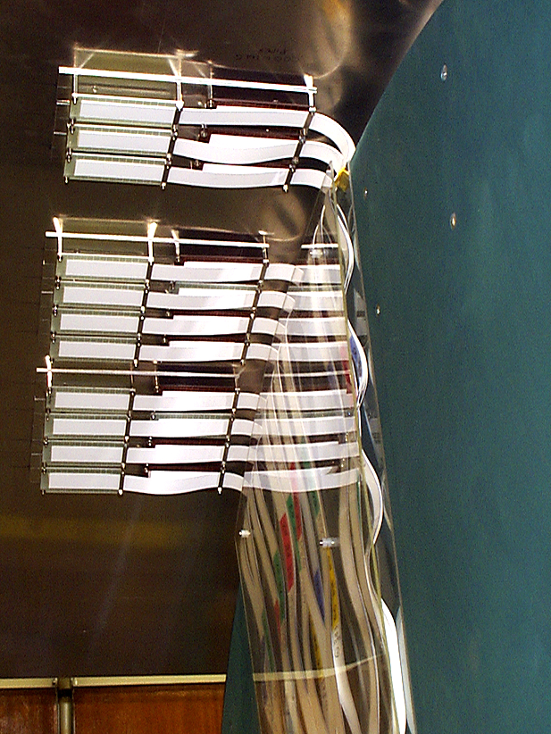
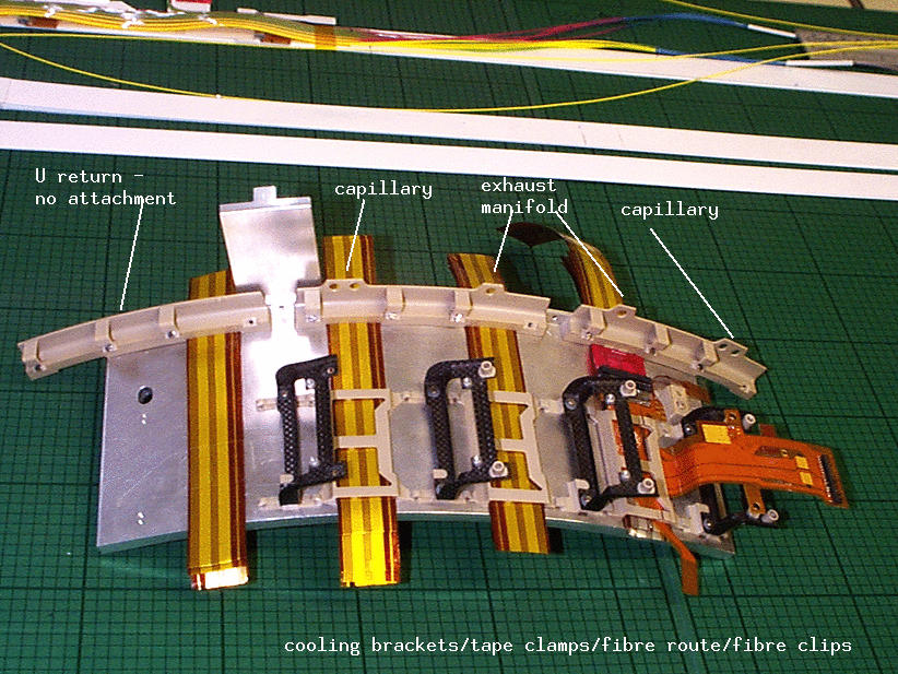
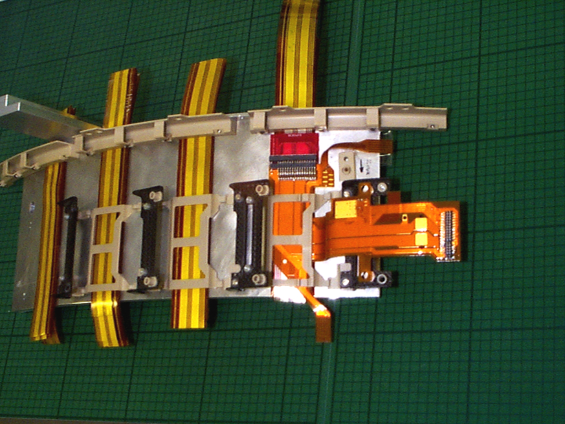
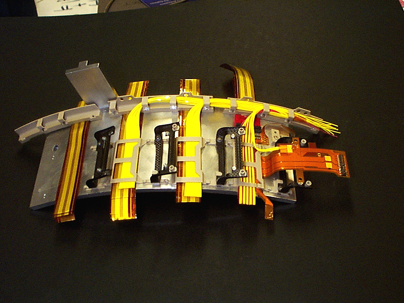
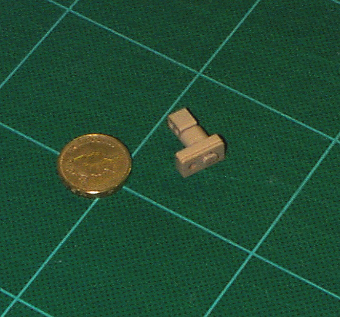
A set of Castellation Clamps have been tried out on the small barrel 3 model
The castellation clamps (also known as barrel end tape clamps and cooling brackets) serve as support brackets for the on-barrel cooling units.These clamp/brackets are screwed to the barrel flange castellations.
Each cooling exhaust manifold is supported in two places by these brackets and each input capillary tube is supported where it joins the barrel.
In the region of the U return sections of the cooling unit no support at the barrel end is supplied as these are intended to be 'floating'.
Here is another view of the model section.
Here is a view of the castellation clamps during fibre routing trials.The fibres are held in place with small clips screwed to the clamps. Note that the on-barrel harness clamps used here are a variety of prototypes, not the final version.
07.01.2002
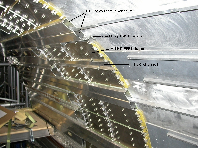
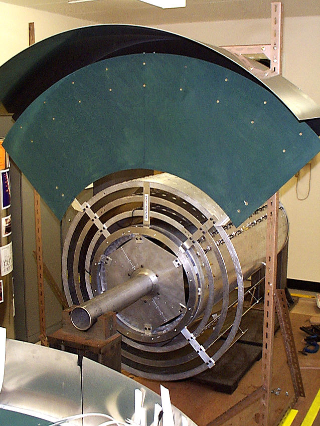
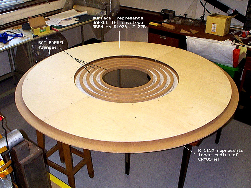
A New Quardrant Sector of the cryostat, PPB1 and the TRT services envelope has been constructed and fixed to the four model barrels now assembled together and is being used to test harness lengths
Model harnesses for one octant of the four barrels (Right-hand and Left-hand) are being made and tested on the four assembled barrels with the patch panel sector.
Here are two model harnesses on the bench, complete with optical fibres and low-mass tapes of the correct length.
Here is a section of the optical fibre part of the harness showing the fibre splice protector .
Here are two harnesses (LH and RH) on the full-scale barrel 3 model before barrel assembly.
The four barrels assembled with the model sector of the cryostat and TRT services envelope (green) and with the model harnesses being fixed in position.
22.10.2001
Provisional Optical Readout Fibre lengths from opto package to splice and from splice to PPB1 connector have been measured
Here is a drawing showing the positions of the fibre bunches and splices on the barrel end
A provisional list of measured readout fibre lengths
has been made. (from opto package on the opto-flex dogleg on the barrel surface via ducts up to MT 12 connectors at PPB1 only) ATLAS SCT BARREL DETECTOR MODELLING and PROTOTYPING, at University College London and ASSEMBLY, INTEGRATION and INSTALLATION at the Large Hadron Collider (LHC) at CERN, Geneva
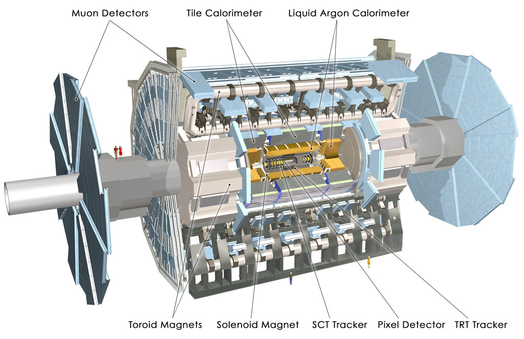